Hybrid glass-sealed electrical connectors

a technology of electrical connectors and glass seals, applied in the direction of coupling device connections, wellbore/well accessories, survey, etc., can solve the problems of increasing hostile environment for these connectors, corroding the environment of natural or chemically enhanced wellbores, and certain disadvantages and limitations of both types of connectors

Active Publication Date: 2005-08-25
RING JOHN H +1
View PDF9 Cites 109 Cited by
  • Summary
  • Abstract
  • Description
  • Claims
  • Application Information

AI Technical Summary

Problems solved by technology

Many of the electrical connectors in the oilfield are exposed to the environment of the open well bore, where at maximum depth, pressures rise to over 30,000 psig, temperatures exceed 500° F., and the natural or chemically-enhanced well bore environment is extremely corrosive.
However, as wells have gone deeper and simultaneous temperature and pressure conditions have increased, the environment for these connectors has become increasingly hostile, and certain disadvantages and limitations of both types of connectors have come to light.
The more common failure mode for glass-sealed connectors is caused by the almost inevitable presence of moisture and by well bore chemicals, either of which can cause current to arc, or short, from the conductor to the metal body of the connector.
Because glass-sealed connectors utilize a metal shell to house the glass-sealed pin conductors, the presence of moisture in the vicinity of the pins may cause arcing or electrical leakage between pins or from pins to ground.
Although expensive because they require that the electrical apparatus be pulled from the well, most such electrical failures are repairable in that the apparatus can be repaired and the connector replaced.
Conditions are improved in connectors in which ceramic insulation extends the insulating distance, or arc path, but the problem is not solved by the use of such materials.
This differential expansion problem was recognized in the afore-mentioned U.S. Pat. No. 3,793,608, and may result in the electrical failure described above.
Because space limitations frequently require pin patterns that are closely spaced in the connector and the ceramic material is not strong in flexural strength, the extended ceramic may become cracked internally, for instance, when a pin is bent and then straightened out.
The damage to the ceramic is almost impossible to detect visually and with the presence of moisture, frequently leads to arcing, electrical leakage, and direct shorts.
Further, the short may be unexpected because the connector, or even the electrical apparatus having the connector installed thereon, tested normally on the surface (at room temperature and in a dry environment), but when the electrical apparatus is run downhole, the short suddenly appears.
However, ceramics are brittle, and oilfield personnel are not well known for their careful handling of equipment such that connectors including ceramic materials are prone to the kind of electrical failure described above when a pin is bent, for instance.
Further, in the higher temperature environments of the wells currently being drilled, even connectors comprised of ceramic materials suffer from the above-characterized problem of differential thermal expansion and the resulting electrical failure.
However, in adverse conditions, a problem that has arisen with some connectors having such a plastic “cap” is that it is possible for water to accumulate under the cap.
When water accumulates under the cap of such connectors, the water provides an electrically conductive path between the pins and / or between the pins and the metal body that results in an undesired electrical leakage or a distortion in the electrical signal from the electrical apparatus.
This second failure mode is referred to as hydraulic leakage and is the more disastrous in that it results in serious and expensive damage to the electrical apparatus and, in the case of an electrical apparatus that is a downhole tool or instrument, expensive and embarrassing lost time on the rig floor because the entire tool must be pulled from the well and rebuilt or replaced.
In some cases, the molded pin can move enough to cause an interruption in the electrical signal, and in others the plastic flows enough to cause a hydraulic failure.
In this failure mode, either through mishandling or because the connector is subjected to conditions that exceed the capabilities of the materials or the construction of the connector, the integrity of the connector is compromised.
As a result of such hydraulic failure, the connector becomes the route for the ingress of steam, water, or other fluid(s) from the well bore and into the electrical apparatus, driven by the high downhole pressure, and hence the electrical apparatus is severely damaged or destroyed.

Method used


Image

  • Hybrid glass-sealed electrical connectors
  • Hybrid glass-sealed electrical connectors
  • Hybrid glass-sealed electrical connectors

Examples


second embodiment

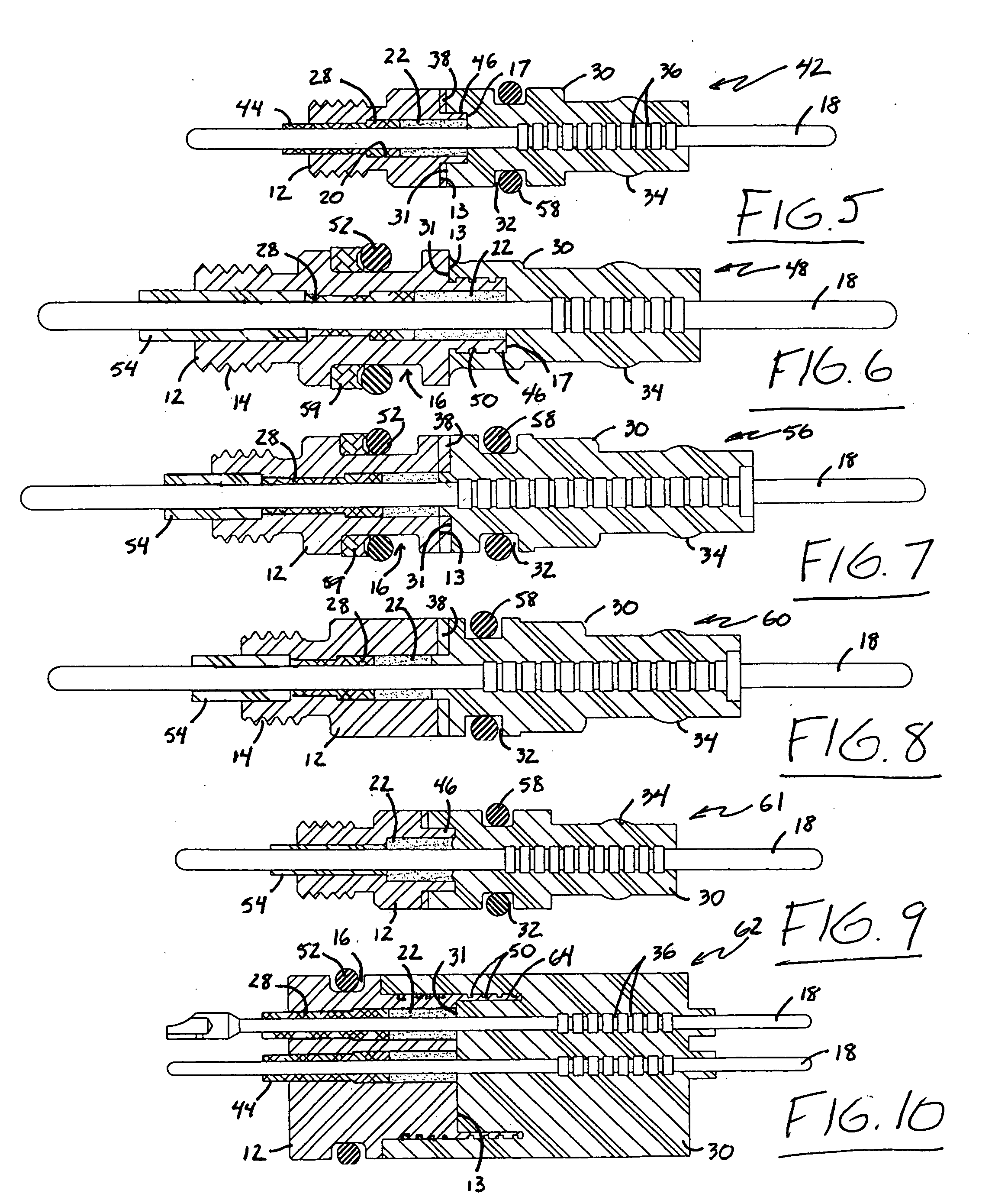
[0047] Referring now to FIG. 5, a connector constructed in accordance with the present invention is indicated generally at reference numeral 42. Connector 42 is comprised of the same component parts as connector 10 shown in FIG. 1 such that the same reference numerals are used to designate the common parts of both embodiments, but connector 42 is intended for use in different applications than the connector 10 shown in FIGS. 1-4 in that the metal body 12 of connector 42 lacks a groove such as the groove 16 in the body 12 of connector 10 (FIGS. 1-4) for an O-ring for effecting the above-described seal with the bulkhead (not shown) of the electrical apparatus to which the body 12 is engaged. Another difference between connector 42 and connector 10 can be seen by reference to the annulus between the O.D. of conductor 18 and the I.D. of the bore 20 through metal body 12. Instead of rings of ceramic material on both the high and low pressure sides of the glass seal 22 such as the ceramic...

third embodiment

[0048] the connector of the present invention is shown at reference numeral 48 in FIG. 6. In the connector 48, the O.D. of nipple 46 is provided with a plurality of grooves 50 such that, when jacket 30 is overmolded onto body 12, the connection is even more secure than in the connector 42 shown in FIG. 5. By comparison of the connector 48 in FIG. 6 to the connectors 10 and 42 in FIGS. 1-5, it can be seen that no groove is provided for an O-ring on the O.D. of jacket 30 such that the connector 48 seals only to the bulkhead (not shown) of the electrical apparatus to which the metal body 12 is threadably engaged. An O-ring 52 and back-up ring 59 are shown in the groove 16 for that purpose. It can also be seen that the connector 48 is provided with an insulating, flexible sleeve 54 on the low pressure side of the ceramic insulator 28 to provide some flexibility and / or vibration resistance to the connector 48 and to decrease the likelihood of damage to the ceramic insulator 28 from bendi...

fourth embodiment

[0049] a connector constructed in accordance with the present invention is indicated generally at reference 56 in FIG. 7. Both the O-ring 52 in groove 16 and the O-ring 58 in groove 32 for effecting independent primary and secondary seals are shown in FIG. 7. Those skilled in the art who have the benefit of this disclosure will recognize that, although not required in all applications, it may be advantageous to provide back-up rings 59 for better effecting the seal between the O.D. of connector 56 and the bulkhead of the electrical apparatus to which connector 56 is engaged.


PUM


Abstract

An electrical connector adapted for mounting to an electrical apparatus used in either high pressure or high temperature, or both high temperature and high pressure, applications. A metal body is provided for mounting to the electrical apparatus with at least one conductor for carrying electricity to or from the electrical apparatus extending therethrough and a thermoplastic jacket is applied over the conductors to the end of the metal body that is subjected to either high pressure or high temperature, or both high temperature and high pressure, for sealing around the conductor. An insulative material is interposed between the metal body and the conductor for sealing around the conductor. In addition to providing two independent internal and two independent external seals, the glass-to-metal seal limits cold-flow (creep) of thermoplastic along the pin and through the metal body. This feature effectively eliminates the catastrophic hydraulic failures possible with prior connectors utilizing a pin, metal body, and high temperature thermoplastic. Because of the redundant internal and external seals, the connector provides undistorted electrical performance in the most hostile environments of temperature and pressure.

Description

BACKGROUND OF THE INVENTION [0001] The present invention relates to electrical connectors useful in many applications, but particularly intended for use in hostile environments. More specifically, the present invention relates to single and multi-pin electrical connectors for use in high-pressure, high-temperature applications which commonly occur in the oilfield, but which are also encountered in geothermal and research applications. [0002] Oil wells are being drilled to deeper depths and encountering harsher conditions than in the past. Many of the electrical connectors in the oilfield are exposed to the environment of the open well bore, where at maximum depth, pressures rise to over 30,000 psig, temperatures exceed 500° F., and the natural or chemically-enhanced well bore environment is extremely corrosive. In part because of these conditions, many downhole tools are oil-filled, but regardless of whether the tools are oil- or air-filled, the high temperatures and pressures of oi...

Claims


Application Information

Patent Timeline
Patent Type & Authority Applications(United States)
IPC IPC(8): H01R13/52
CPCH01R13/521H01R13/533H01R13/5216E21B47/12E21B17/023
Inventor RING, JOHN H.RING, RUSSELL K.
Owner RING JOHN H
Why Eureka
Try Eureka