
Architecture for controlling access to a service by concurrent clients

a concurrent client and server technology, applied in the field of server architecture, can solve the problems of increasing operations expenses, increasing operations expenses, and burdening both subscriber and service provider to explicitly maintain lists

Inactive Publication Date: 2005-08-25
MICROSOFT TECH LICENSING LLC
View PDF22 Cites 117 Cited by
  • Summary
  • Abstract
  • Description
  • Claims
  • Application Information

AI Technical Summary

Benefits of technology

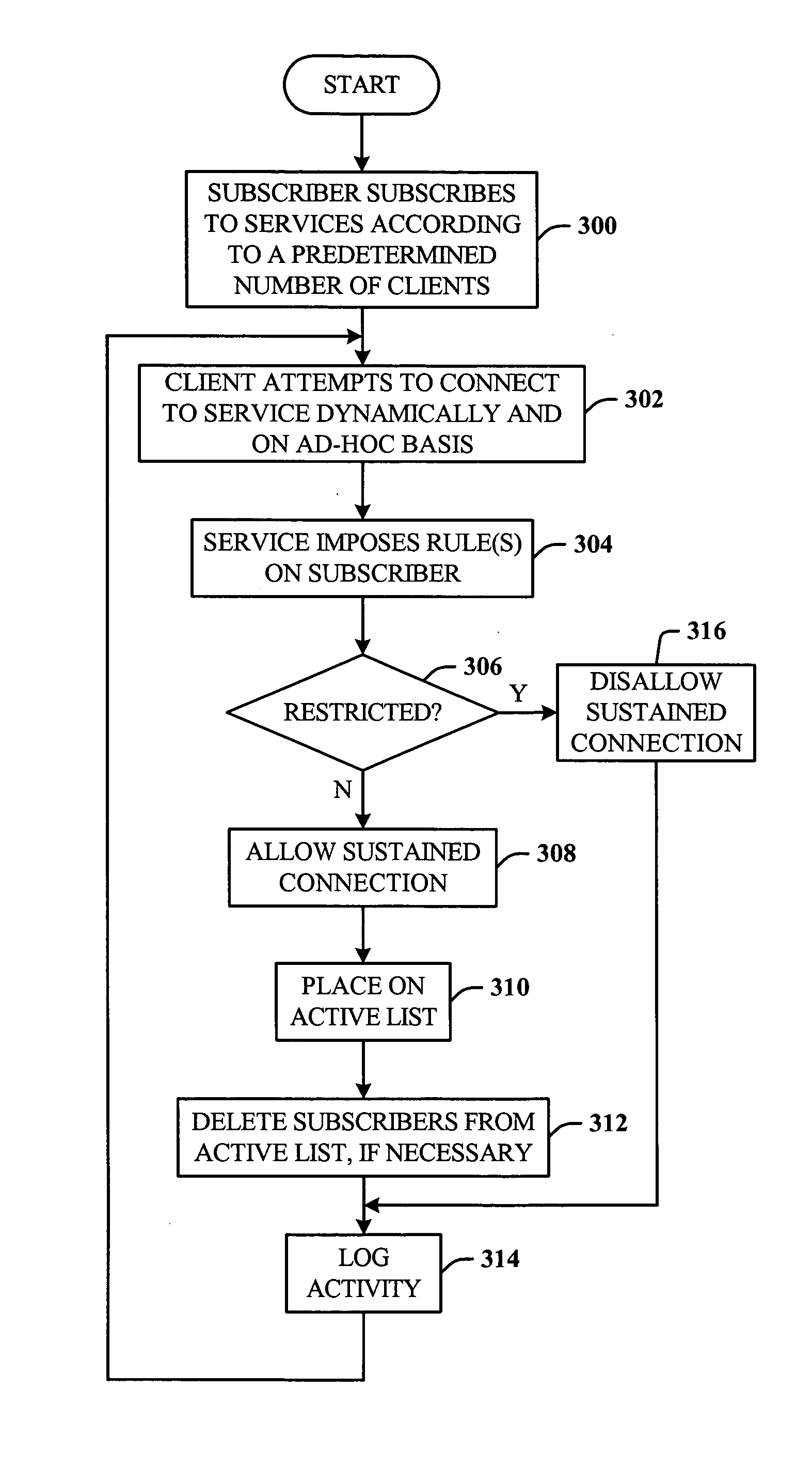
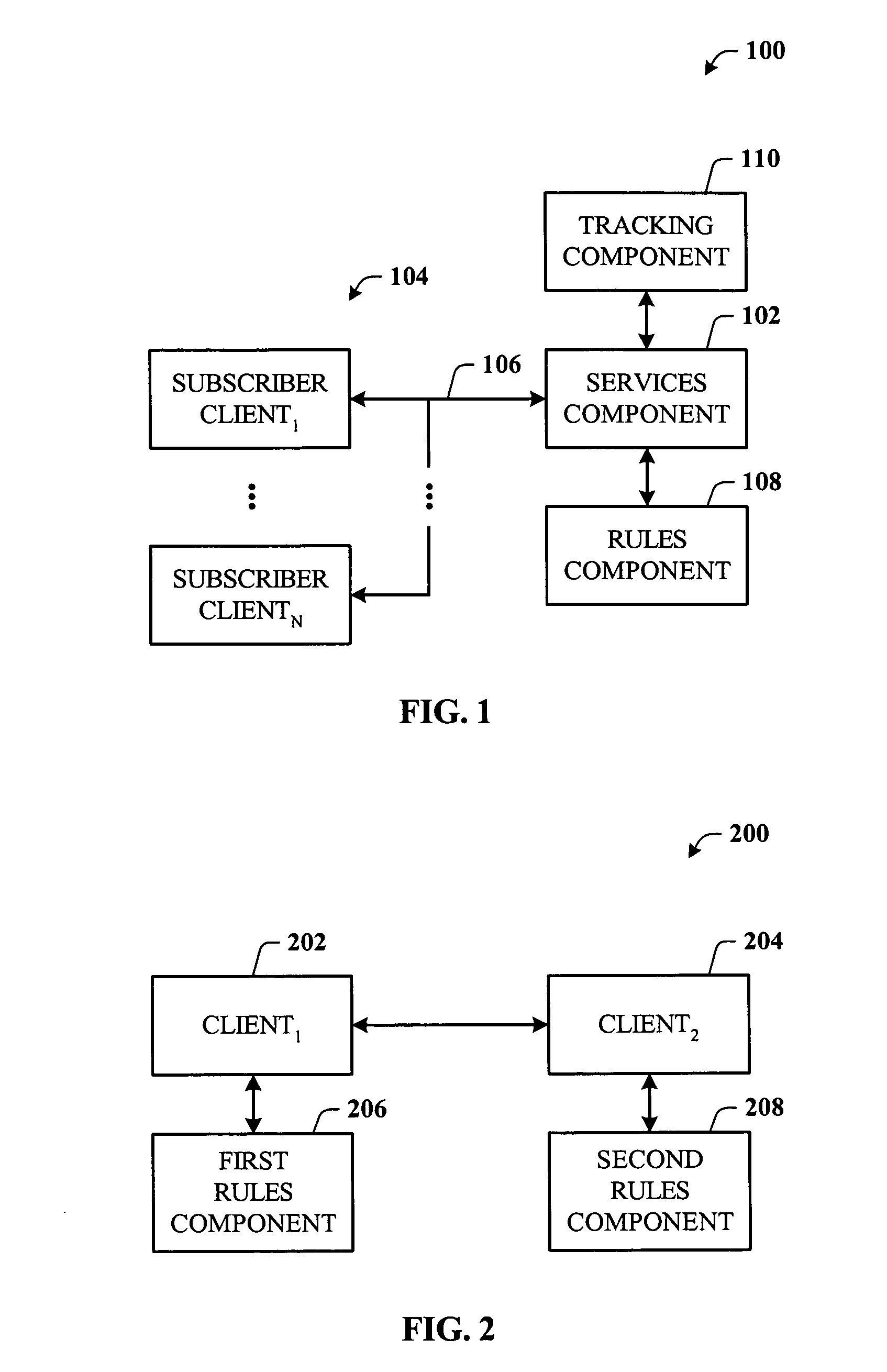
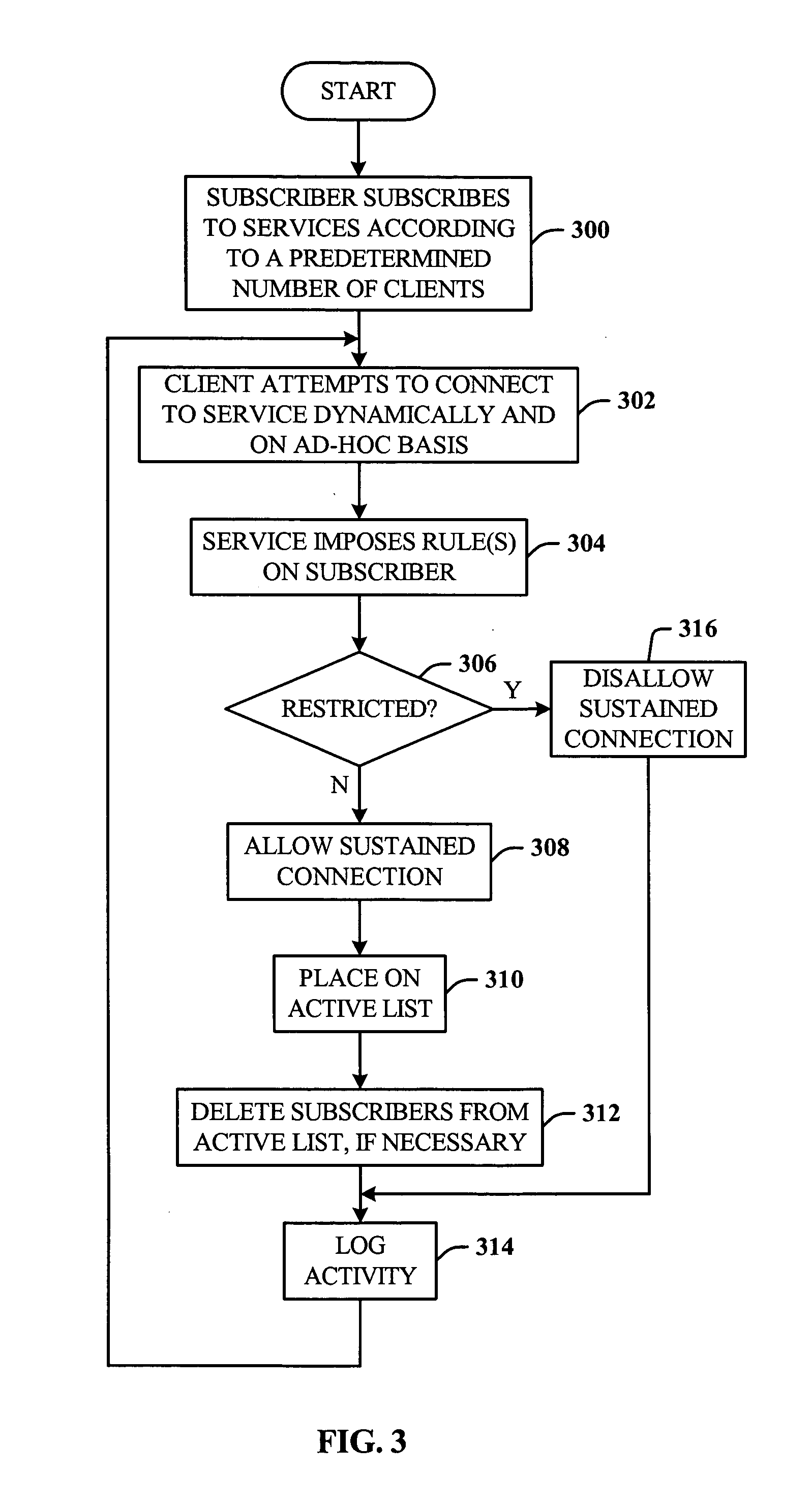
The present invention is a subscription service that allows client machines to subscribe and enter dynamically and on an ad-hoc basis. The service enforces rules to limit the number of simultaneous clients and prevents churn (replacing old machines with new ones) and frequency (how often a client can leave and re-enter service in a given period of time). The invention simplifies the process of managing the service and reduces the need for an administrator. Overall, the invention provides a more efficient and flexible way to manage a subscription service.

Problems solved by technology

One challenge with such a mechanism is enforcing a policy or rule that the subscriber is prevented from having more than “n” concurrently active clients.
One disadvantage of this method is that it places a burden on both the subscriber and the service provider to explicitly maintain lists.
The service provider may have to maintain computer-based and telephone-based service center resources to facilitate the maintenance of these lists, which leads to an increased operations expense.
The subscriber must maintain a strict database that is up to date or the desired level of service will fail, which also leads to an increased operations expenses.
For example, if the subscriber connects a new client to the service, and simply chose to retire an old client, the subscriber cannot do so without access to the list.
In a large organization, this represents another burden on the Information Technology administration staff.
One limitation of the license server approach is as follows.

Method used


Image

  • Architecture for controlling access to a service by concurrent clients
  • Architecture for controlling access to a service by concurrent clients
  • Architecture for controlling access to a service by concurrent clients

Examples


Embodiment Construction

[0022] The present invention is now described with reference to the drawings, wherein like reference numerals are used to refer to like elements throughout. In the following description, for purposes of explanation, numerous specific details are set forth in order to provide a thorough understanding of the present invention. It may be evident, however, that the present invention may be practiced without these specific details. In other instances, well-known structures and devices are shown in block diagram form in order to facilitate describing the present invention.

[0023] As used in this application, the terms “component” and “system” are intended to refer to a computer-related entity, either hardware, a combination of hardware and software, software, or software in execution. For example, a component may be, but is not limited to being, a process running on a processor, a processor, an object, an executable, a thread of execution, a program, and / or a computer. By way of illustrat...


PUM


Abstract

Architecture for controlling access to a service. The architecture allows denial of regular and periodic service to all but a selected number of concurrent clients associated with a subscriber, and without any manual administration at the server of a list of specific computers. Rather than require an administered list, the system discovers which clients are active, places the active clients on an active list, and excludes all client not on the active list. The system includes one or more rules the enforcement of which provide a mechanism for ensuring that the subscriber is not adding an unlimited number of clients or rotating clients in and out of the pool to effectively maintain service on a larger number of computers to which the subscriber is entitled.

Description

TECHNICAL FIELD [0001] This invention is related to software servers systems, and more specifically, to server architecture that facilitates subscriber tracking and administration. BACKGROUND OF THE INVENTION [0002] A subscription can be issued or purchased that entitles a subscriber to a predetermined number (symbolically “n”) of concurrently active clients, where each client runs on a separate machine, and the subscription entitles the clients to access services on a central server. Each client can require periodic but regular service from a server. One challenge with such a mechanism is enforcing a policy or rule that the subscriber is prevented from having more than “n” concurrently active clients. At the same time, it is important to ensure that the subscriber is not systematically rotating the clients that are accessing the server to effectively obtain more service for which they are entitled. [0003] One way to administer this is to assign to each subscriber a unique identifie...

Claims


Application Information

Patent Timeline
Patent Type & Authority Applications(United States)
IPC IPC(8): G06F15/00G06F12/00G06F12/14G06F15/16G06F17/00G06F17/30H04L12/00H04L12/14H04L12/24H04L12/66H04L29/06H04L29/08
CPCH04L12/1432H04L12/66H04L41/5022H04L41/5048H04L67/02H04L63/126H04L67/30H04L67/22H04L63/0823H04L67/535A23B7/005F26B3/082
Inventor KRAMER, MICHAELSEINFELD, MARC
Owner MICROSOFT TECH LICENSING LLC
Learn More