Solid propellant gas generators in power systems

a technology of power system and solid propellant, which is applied in the direction of machines/engines, sustainable transportation, climate sustainability, etc., can solve the problems of two-part liquid propellant system, weight and cost, complexity, weight and cost of aircraft, and weight and cost associated problems

Inactive Publication Date: 2005-09-01
HONEYWELL INT INC
View PDF10 Cites 19 Cited by
  • Summary
  • Abstract
  • Description
  • Claims
  • Application Information

AI Technical Summary

Benefits of technology

[0017] In yet a further aspect of the present invention, an emergency power system comprises a plurality of solid propellant gas generators each having a gas outlet in fluid communication with a turbine wheel rotationally disposed within a gas turbine housing, a fixed area flow restriction orifice disposed between, and in fluid communication with, the gas outlet and the turbine wheel; and in fluid communication with, the gas outlet and the turbine wheel; a vent valve in fluid communication with the gas outlet capable of providing fluid communication between the gas outlet and an external environment; a compressed gas assist valve having a compressed gas assist valve inlet in fluid communication with a compressed gas tank, wherein the compressed gas assist valve is capable of providing fluid communication between a compressed gas disposed within the compressed gas tank and the turbine wheel through the compressed gas assist valve inlet; a dump valve capable of providing fluid communication between the gas outlet and

Problems solved by technology

However, such systems may require tanks, pumps, controls and the like to store the oxidizer and to meter delivery of the oxidizer and the fuel during operation.
Accordingly, a two-part liquid propellant system may add complexity, weight, and cost to an aircraft.
While such systems may reduce the weight and cost associated with storing and delivering an oxidizer, such systems, may require storage and servicing of a highly reactive fuel, and maintenance of a catalyst bed.
Also, single fuels (e.g., hydrazine) of a one part gas generation system may be toxic, and thus may present safety issues related to fuel toxicity, as well as to explosion hazards.
Maintaining catalyst bed integrity, and preventing fouling or poisoning of the catalyst, may also challenge the reliability of such systems.
However, unlike liquid propellant systems, solid propellant systems may not be turned on and

Method used


Image

  • Solid propellant gas generators in power systems
  • Solid propellant gas generators in power systems
  • Solid propellant gas generators in power systems

Examples


Embodiment Construction

[0024] The following detailed description is of the best currently contemplated modes of carrying out the invention. The description is not to be taken in a limiting sense, but is made merely for the purpose of illustrating the general principle of the invention, since the scope of the invention is best defined by the appended claims.

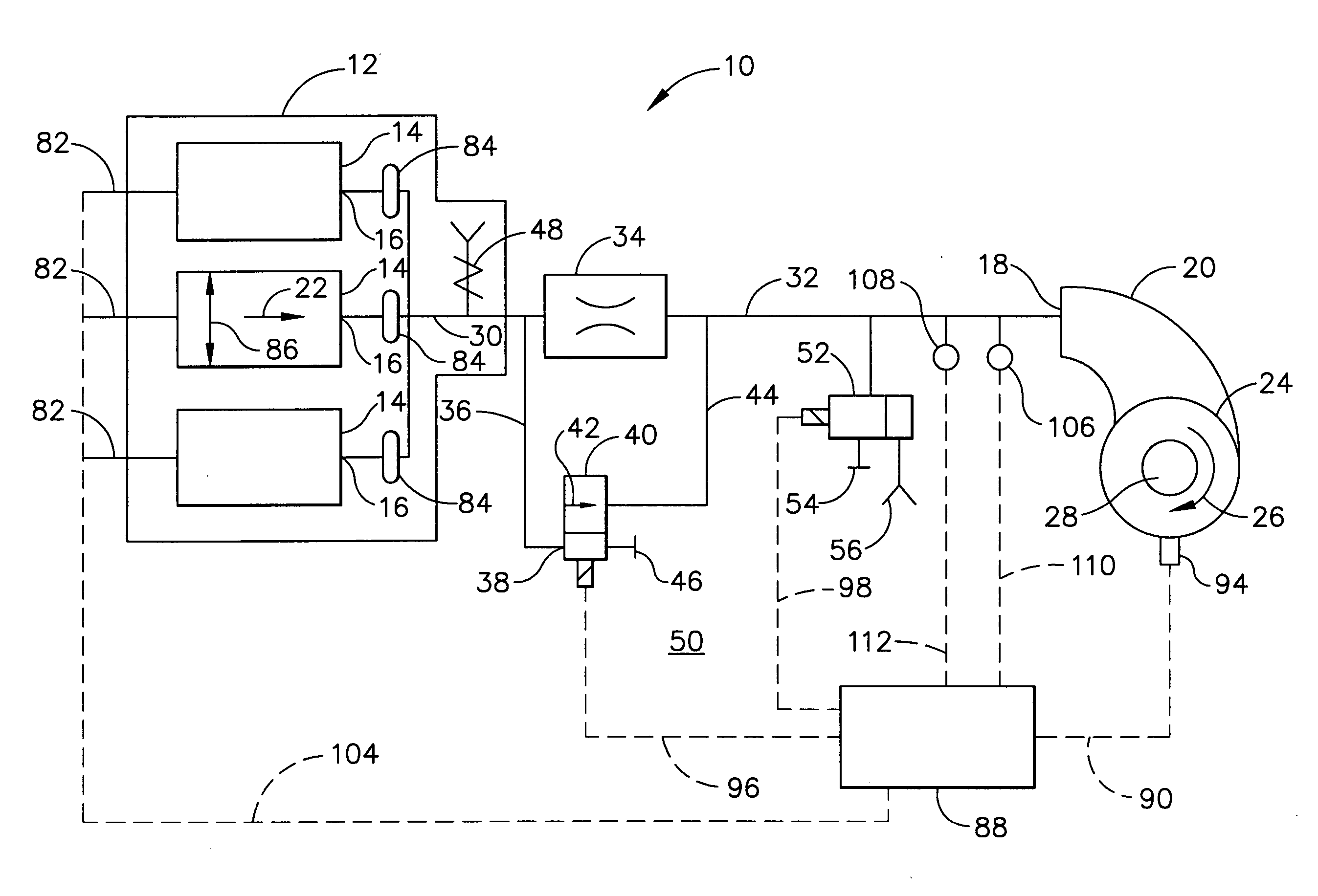
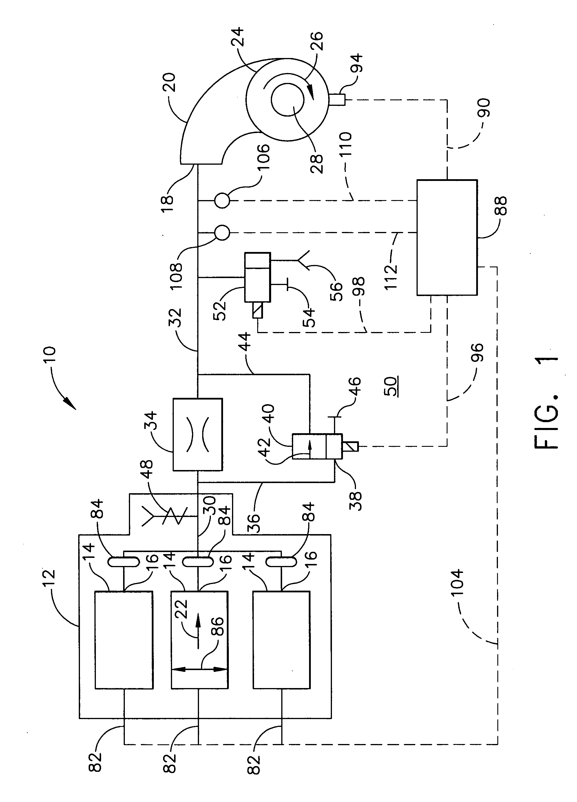
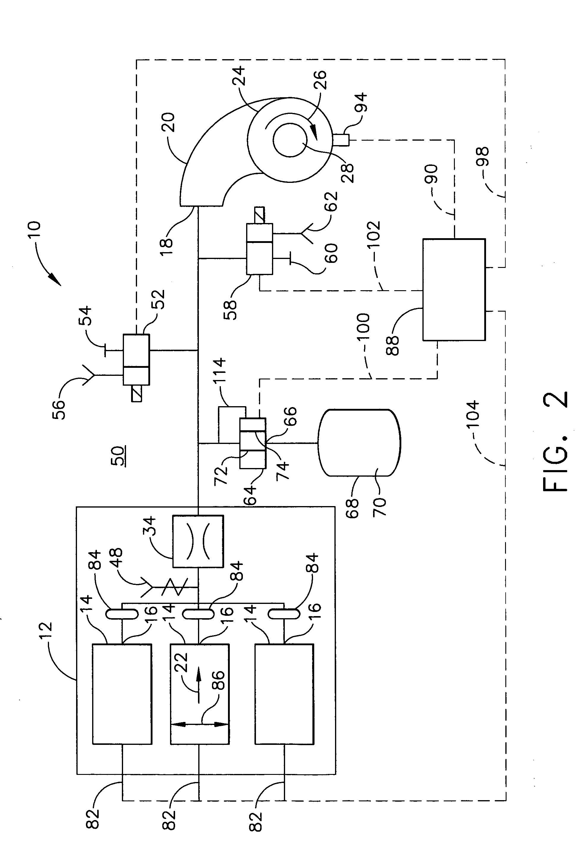
[0025] The present invention generally provides an emergency power system comprising a plurality of solid propellant gas generators, each having a gas outlet in fluid communication with a gas turbine inlet of a gas turbine housing. Actuation of the solid propellant gas generator may produce delivery of a quantity of gas at a pressure sufficient to turn a turbine wheel rotationally disposed within the gas turbine housing. The turbine wheel may then be in rotational communication with an input shaft of a pump and / or a generator which may be required to operate systems aboard an aircraft or other vehicle. This is unlike the prior art, wherein a solid prop...


PUM


Abstract

An emergency power system comprising a plurality of solid propellant gas generators each having a gas outlet in fluid communication with a turbine wheel rotationally disposed within a gas turbine housing, the turbine wheel being in rotational communication with an electric generator input shaft, a fluid pump input shaft, or both. A method of producing power from such an emergency power system is also disclosed.

Description

BACKGROUND OF THE INVENTION [0001] The present invention generally relates to apparatus and methods for an emergency power system. More specifically, the present invention relates to an emergency power system comprising a plurality of solid propellant gas generators operable to produce a quantity of gas at a sufficient pressure for delivery to a turbine power unit (TPU) to provide output power as a part of an emergency power system (EPS). [0002] Vehicles such as aircraft may include an environmental control system for providing temperature conditioned, pressurized air to the pilot, passengers, and heat generating electronics; and an auxiliary power unit may be used to supply auxiliary power for the aircraft, typically when either the aircraft is on the ground or flying at low altitudes (e.g., below about 30,000 ft). The aircraft may also include an emergency power unit to provide emergency power in the event of a failure or other condition that may threaten operation of the vehicle....

Claims


Application Information

Patent Timeline
IPC IPC(8): F02C1/00F02C3/26F02C7/272F02C7/32
CPCF02C1/00F02C7/272F05D2220/50Y02T50/671F02C7/32Y02T50/60
Inventor KUNG, RU-LIGOLDBERG, SCOTT J.MORANDO, ALEXILES, TOM
Owner HONEYWELL INT INC
Why Eureka
Try Eureka