Apparatus and method for manufacturing optical fiber including rotating optical fiber preforms during draw

a technology of optical fiber and preform, which is applied in the field of optical fiber, can solve the problems of optical fiber loss, fiber cladding non-circularity, fiber curl, etc., and achieve the effects of improving the uniformity of optical fiber preform geometry, reducing transmission loss and splicing loss in the drawn optical fiber, and improving transmission qualities

Inactive Publication Date: 2005-09-01
FURAKAWA ELECTRIC NORTH AMERICA INC
View PDF11 Cites 10 Cited by
  • Summary
  • Abstract
  • Description
  • Claims
  • Application Information

AI Technical Summary

Benefits of technology

[0009] The invention is embodied in a method and apparatus for manufacturing optical fiber having improved transmission qualities. The method includes providing an optical fiber preform from which to draw optical fiber, rotating the optical fiber preform about its longitudinal axis as the preform is passed through the heating zone of a draw furnace, and drawing optical fiber from the rotating preform. Rotating the optical fiber preform in a relatively moderate, controlled manner improves the uniformity of the optical fiber preform geometry as optical fiber is being drawn therefrom, which, in turn, reduces transmission loss and splicing loss in the optical fiber drawn. According to embodiments of the invention, rotation of the optical fiber preform is constant or variable, and is in one or both directions (e.g., clockwise and / or counter-clockwise). Embodiments of the invention also include a method for manufacturing optical fiber in which the optical fiber preform is rotated as it passes through the draw furnace and a spin is imparted on optical fiber after it has been drawn from the rotating preform. Embodiments of the invention improve overall optical fiber geometry by reducing optical fiber geometric deformities, fiber PMD and their associated optical fiber transmission loss.

Problems solved by technology

Many forms of optical fiber loss are attributable to geometrical deformities present in optical fiber, which often result from conventional optical fiber manufacturing processes.
Conventionally, inhomogeneous material distribution in the preform and / or non-uniform thermo processing (heating and cooling) during the fiber drawing process often cause fiber maladies such as fiber curl, fiber cladding non-circularities, and longitudinal variation of the fiber core region and the fiber cladding region.
Such fiber geometric deformities contribute to fiber loss such as loss associated with splicing two optical fibers together, e.g., because of fiber cladding diameter variances between the spliced fibers.
However, because many fiber geometric deformities are caused by initial optical fiber preform deformities such as preform ovality and non-circularity of preform cladding regions, spinning optical fiber after it is drawn from the preform may have limited effect on overall fiber geometries.
However, in these approaches, the preform spin rates needed for advantageous results are in the range from approximately 2400-6000 revolutions per minute (rpm), which spin rates are unsuitably high for commercial fiber production.

Method used


Image

  • Apparatus and method for manufacturing optical fiber including rotating optical fiber preforms during draw
  • Apparatus and method for manufacturing optical fiber including rotating optical fiber preforms during draw
  • Apparatus and method for manufacturing optical fiber including rotating optical fiber preforms during draw

Examples


Embodiment Construction

[0012] In the following description like reference numerals indicate like components to enhance the understanding of the invention through the description of the drawings. Also, although specific features, configurations and arrangements are discussed hereinbelow, it should be understood that such is done for illustrative purposes only. A person skilled in the relevant art will recognize that other steps, configurations and arrangements are useful without departing from the spirit and scope of the invention.

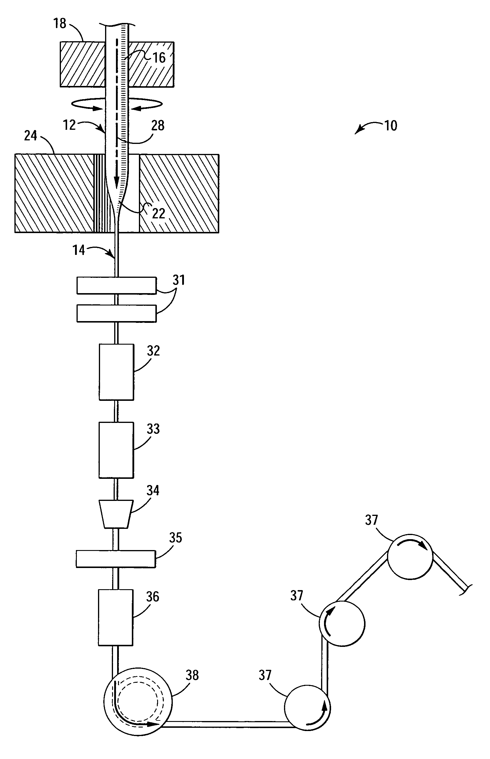
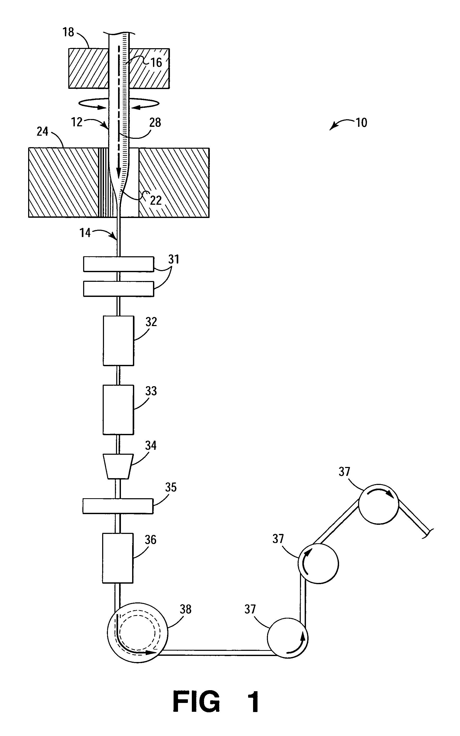
[0013] Referring now to FIG. 1, shown is a simplified, cross-sectional view of an apparatus 10 for manufacturing optical fiber according to embodiments of the invention. Typically, optical fiber is manufactured by gradually heating an optical fiber preform 12 and drawing the heated portion of the preform into optical fiber (shown generally as 14). The preform 12 is heated by a heat source such as a furnace or draw furnace 24. The preform 12 typically is vertically suspended from...


PUM

PropertyMeasurementUnit
rotation rateaaaaaaaaaa
heataaaaaaaaaa
rate of rotationaaaaaaaaaa

Abstract

Embodiments of the invention include a method and apparatus for manufacturing optical fiber. The optical fiber manufacturing method includes providing an optical fiber preform from which to draw optical fiber, rotating the optical fiber preform about its longitudinal axis as the preform is being passed through the heating zone of a draw furnace, and drawing optical fiber from the rotating preform. Rotating the optical fiber preform in a relatively moderate, controlled manner improves the uniformity of the optical fiber preform geometry as optical fiber is being drawn therefrom, which, in turn, reduces transmission loss and splicing loss in the drawn optical fiber. Rotation of the optical fiber preform is constant or variable, and occurs in one or both directions. Embodiments of the invention also include a method for manufacturing optical fiber in which the preform is rotated as it passes through the furnace and a spin is imparted on optical fiber drawn from the rotated preform. Embodiments of the invention improve overall optical fiber geometry by reducing optical fiber geometric deformities, PMD and their associated optical fiber transmission loss.

Description

BACKGROUND OF THE INVENTION [0001] 1. Field of Invention [0002] The invention relates to optical fiber. More particularly, the invention relates to apparatus and methods for manufacturing optical fiber having reduced polarization mode dispersion (PMD) and improved geometric uniformity. [0003] 2. Description of Related Art [0004] Within the field of optical fiber manufacturing, many techniques have been used to produce optical fiber having improved qualities such as reduced optical loss and reduced polarization mode dispersion (PMD). Many forms of optical fiber loss are attributable to geometrical deformities present in optical fiber, which often result from conventional optical fiber manufacturing processes. In general, optical fibers typically are manufactured in a draw tower by vertically suspending an optical fiber preform and moving it into a draw furnace at a controlled rate. The preform softens in the furnace and optical fiber is drawn from the softened end of the preform rod ...

Claims


Application Information

Patent Timeline
Patent Type & Authority Applications(United States)
IPC IPC(8): C03B37/027C03B37/029
CPCC03B37/02745C03B37/029C03B2203/19C03B2205/74C03B2203/36C03B2205/06C03B2205/07C03B2203/20
Inventor ZHIOU, ZHI
Owner FURAKAWA ELECTRIC NORTH AMERICA INC
Why Eureka
Try Eureka