Ballistic resistant turret and method of making same

Inactive Publication Date: 2005-09-01
U S GLOBAL NANOSPACE
View PDF30 Cites 56 Cited by
  • Summary
  • Abstract
  • Description
  • Claims
  • Application Information

AI Technical Summary

Benefits of technology

[0006] It is an object of the present invention to provide an a

Problems solved by technology

The steel turret ring, while improving ballistic protection, adds new dangers.
The vehicle is less stable and prone to tippin

Method used


Image

  • Ballistic resistant turret and method of making same
  • Ballistic resistant turret and method of making same
  • Ballistic resistant turret and method of making same

Examples


Example

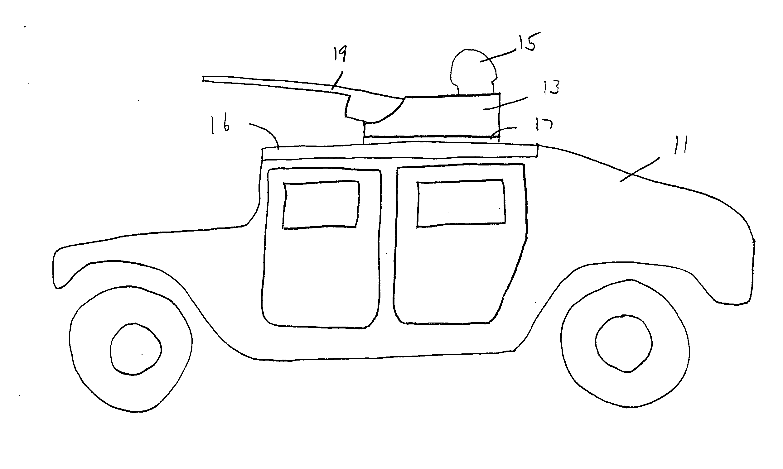
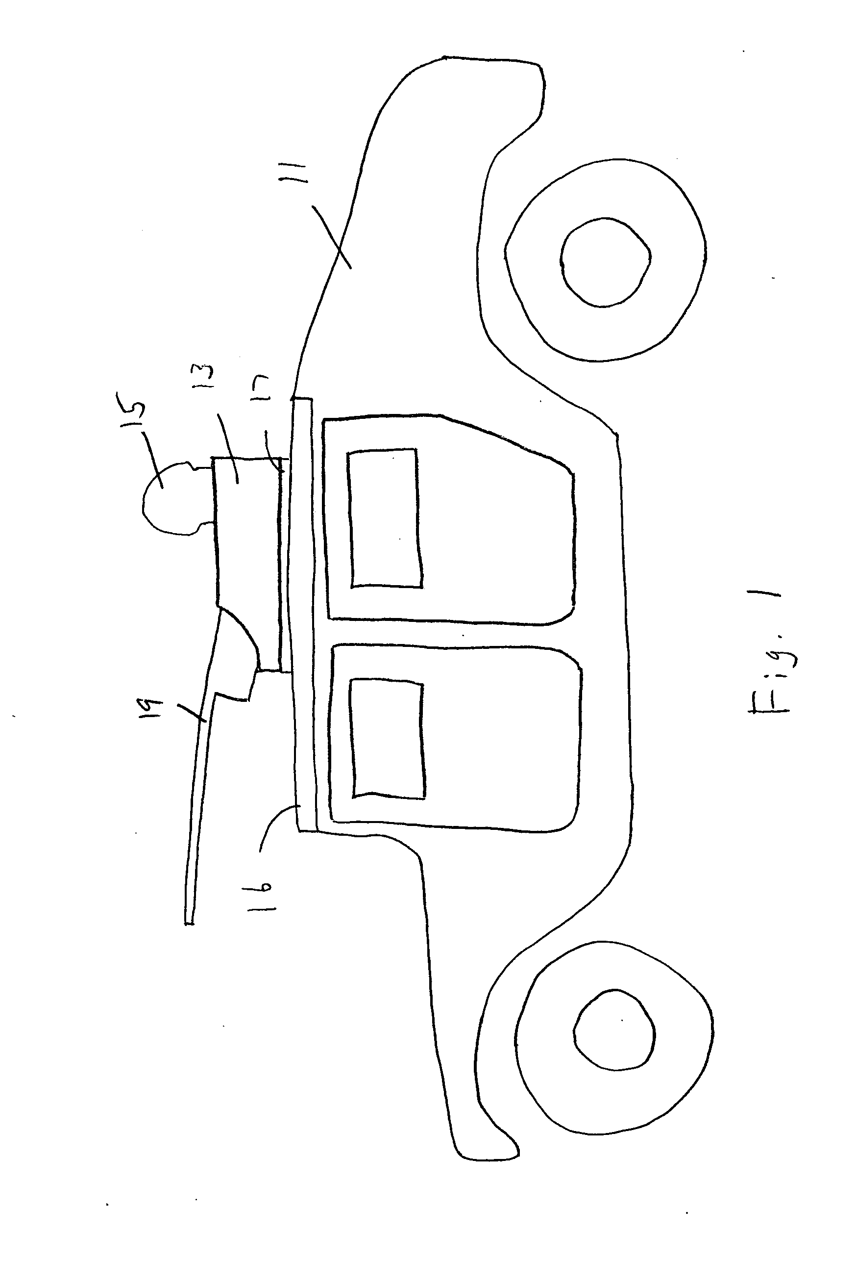
[0025]FIG. 1 shows a vehicle 11 that is equipped with a turret 13 of the present invention, in accordance with a preferred embodiment. The turret 13 is a ring-shaped wall that surrounds the gunner 15 in the vehicle. The gunner 15 stands on the floorboards of the vehicle; his upper body protrudes through an opening in the roof 16. Surrounding the opening is a bearing ring 17. Mounted to the bearing ring 17 is a machine gun 19 or other equipment. The turret 13 is also mounted to the bearing ring 17. The turret 13 and the gun 19 can rotate or swing on the bearing ring 17 horizontally relative to the roof 16.

[0026] The turret 13 provides a ballistic resistant wall around the upper body of the gunner 15. The turret 13 provides protection against direct gunfire (such as a bullet striking the turret wall), up to National Institute of Justice (NIJ) level IV protection, and also protection from fragmentation ballistic particles (such as shrapnel). In the preferred embodiment, the turret wei...


PUM


Abstract

A turret is rotatably mounted to the roof of a vehicle such as a HMMWV and provides ballistic protection to an individual inside. The turret wall has one or more layers of ceramic tiles set in a polymer resin reinforced with nanoparticles. A nonwoven material backs the ceramic layers to spread an impact over a larger surface area. A laminated multiply nanofiber textile layer is in back of the ceramic layers to stop fragments form penetrating through the turret wall. The nanofiber textile plies are laminated together with resin reinforced by carbon nanofibers or nanotubes.

Description

[0001] This application claims the benefit of provisional patent application Ser. No. 60 / 481,080, filed Jul. 11, 2003.FIELD OF THE INVENTION [0002] The present invention relates to armored trucks or vehicles and particularly to turrets for such vehicles. BACKGROUND OF THE INVENTION [0003] Military vehicles, such as the High Mobility Multipurpose Wheeled Vehicle (HMMWV), the Land Rover and the Unimog, frequently have a soldier standing in the rear, manning equipment. Various equipment configurations can be used, such as a machine gun, or reconnaissance viewing optics. The equipment is typically mounted on a bearing so as to allow horizontal rotation. [0004] This position, known as a “gunner” when the machine gun is used, is exposed to fire. A soldier in the gunner position has to rely on his personal body armor for protection. [0005] In the prior art, attempts have been made to provide an armored turret ring of steel around the gunner's position. The steel turret ring, while improvin...

Claims


Application Information

Patent Timeline
IPC IPC(8): F41H5/04F41H5/20
CPCF41H5/20F41H5/0435
Inventor SQUIRES, STEPHEN B.GARDINER, MICHAEL J.
Owner U S GLOBAL NANOSPACE
Why Eureka
Try Eureka