Substrate carrier for parallel wafer processing reactor

a technology of substrate carrier and parallel wafer processing, which is applied in the direction of conveyor parts, transportation and packaging, coatings, etc., can solve the problems of limited throughput of single wafer processing, and achieve the effects of reducing the number of susceptors, increasing the capacity of substrates, and reducing costs

Inactive Publication Date: 2005-09-01
APPLIED MATERIALS INC
View PDF9 Cites 59 Cited by
  • Summary
  • Abstract
  • Description
  • Claims
  • Application Information

AI Technical Summary

Benefits of technology

[0012] The substrate carrier according to embodiments of the present invention offers certain advantages over the prior art substrate carrier desi...

Problems solved by technology

However, single wafer pro...

Method used


Image

  • Substrate carrier for parallel wafer processing reactor
  • Substrate carrier for parallel wafer processing reactor
  • Substrate carrier for parallel wafer processing reactor

Examples


Embodiment Construction

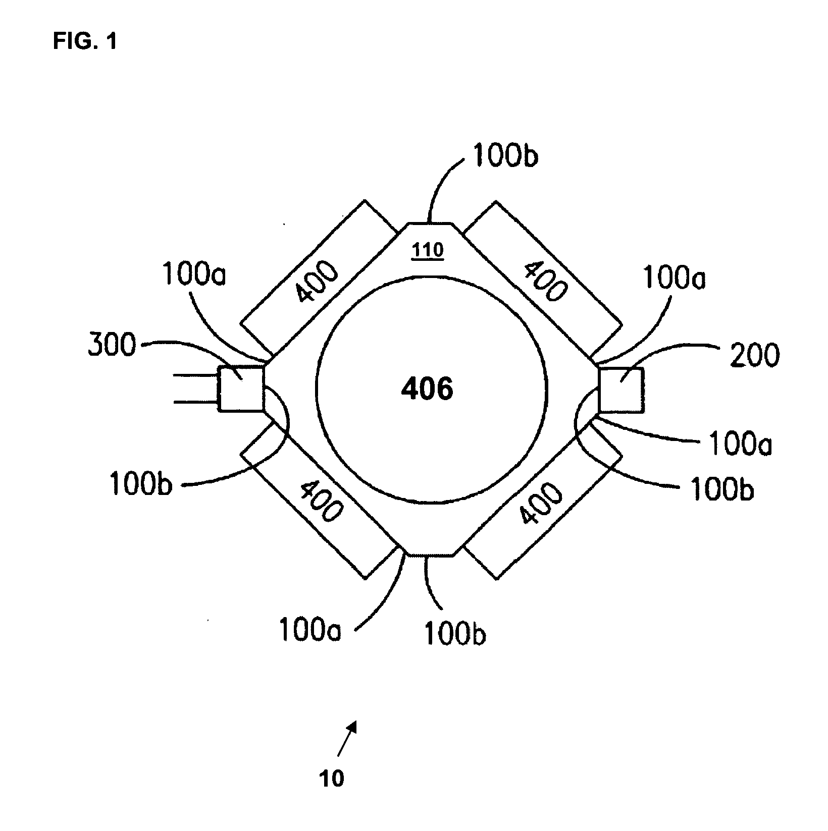
[0027]FIG. 1 provides a cross-sectional top view of a parallel wafer processing reactor 10 as may be employed with certain features of the present invention. The reactor 10 includes four walls 100a and four walls 100b that enclose a processing space 110. A gas injection manifold 200 and a gas exhaust manifold 300 are attached to opposite walls 100b. A multiple zone heating structure 400 is attached to each of the four side walls 100a. A substrate carrier for holding a plurality of wafers or substrates is illustrated as 406.

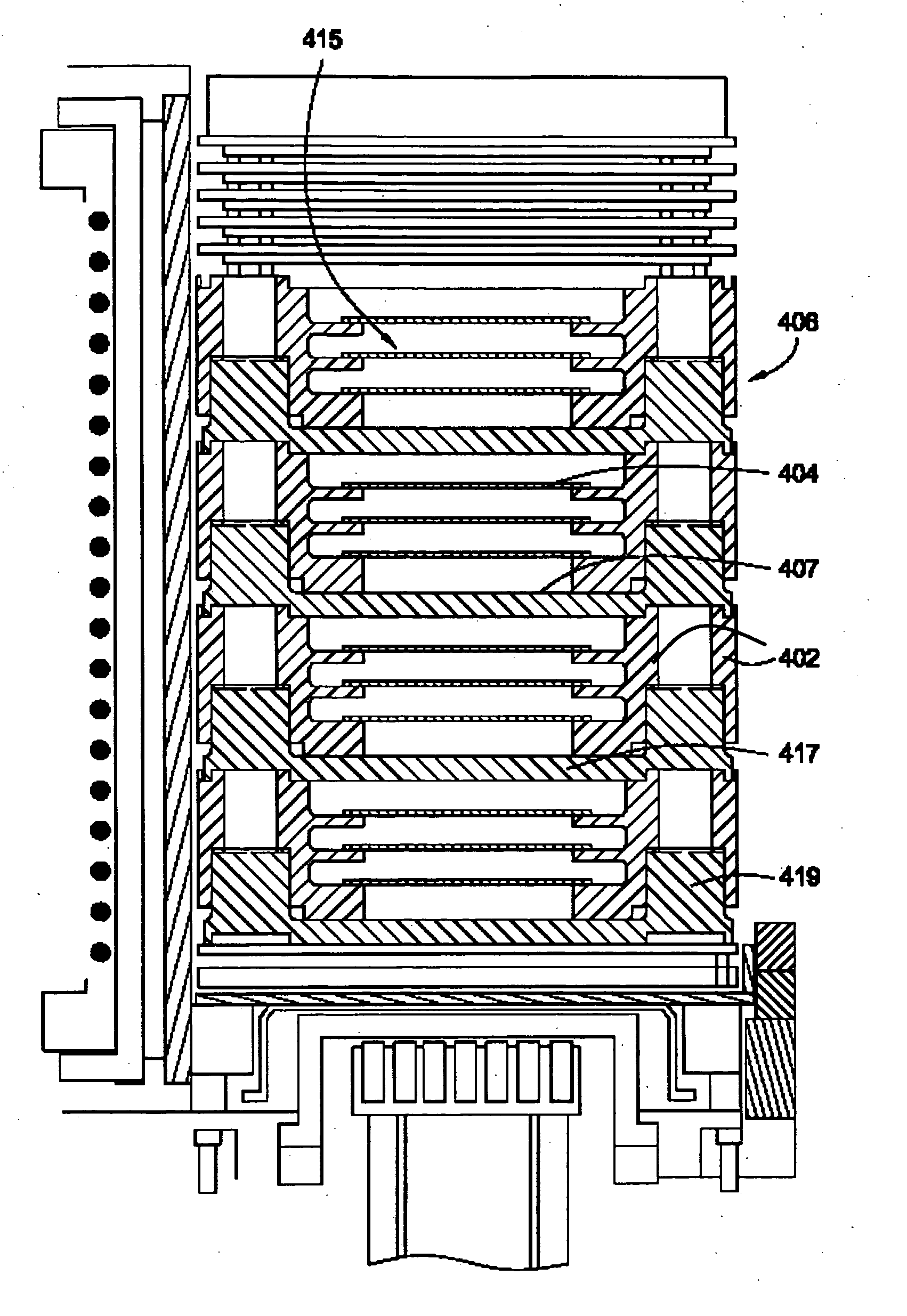
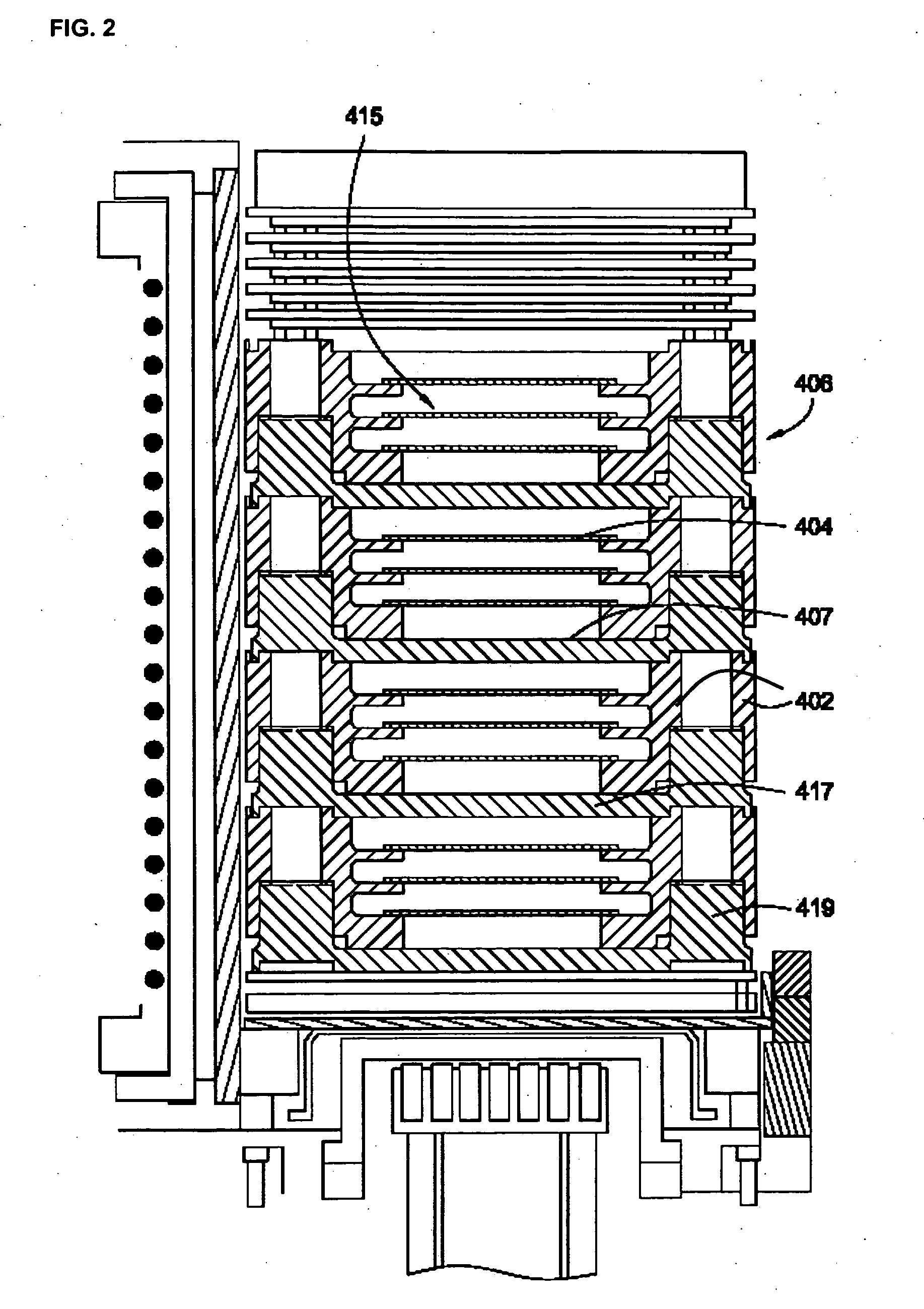
[0028]FIG. 2 provides an enlarged side view of a substrate carrier 406 in accordance with one embodiment of the present invention. The substrate carrier 406 generally defines an elongated cylindrical body. Openings 415 are formed along the longitudinal axis of the substrate carrier 406 between susceptors 407. Substrates 404 are placed in the openings 415 between pairs of susceptors 407 and mounted on shoulders that are formed on spacers 402.

[0029] The susceptors...


PUM


Abstract

A substrate carrier for a parallel wafer processing reactor supports a plurality of substrates. The substrate carrier includes a plurality of susceptors, which may be thermal plates or annular rings that are arranged horizontally in a vertical stack. The substrates are mounted between pairs of susceptors on two or more supports provided around the outer periphery of the susceptors. The number of substrates mounted between each pair of susceptors may the same or different but is two or more between at least one pair of susceptors.

Description

CROSS-REFERENCE TO RELATED APPLICATIONS [0001] This application is a continuation-in-part of U.S. application Ser. No. 10 / 216,079, filed Aug. 9, 2002, which is a continuation-in-part of: (a) U.S. application Ser. No. 09 / 954,705, filed Sep. 10, 2001, now U.S. Pat. No. 6,780,464, which is a continuation-in-part of U.S. application Ser. No. 09 / 396,588, filed Sep. 15, 1999, now U.S. Pat. No. 6,287,635 (which claims the benefit of U.S. Provisional Application Ser. No. 60 / 100,594, filed Sep. 16, 1998), which is a continuation-in-part of: (i) U.S. application Ser. No. 08 / 909,461, filed Aug. 11, 1997, now U.S. Pat. No. 6,352,593, (ii) U.S. application Ser. No. 09 / 228,835, filed Jan. 12, 1999, now U.S. Pat. No. 6,167,837 (which claims the benefit of U.S. Provisional Application Ser. No. 60 / 071,572, filed Jan. 15, 1998), and (iii) U.S. application Ser. No. 09 / 228,840, filed Jan. 12, 1999, now U.S. Pat. No. 6,321,680 (which claims the benefit of U.S. Provisional Application Ser. No. 60 / 071,571...

Claims


Application Information

Patent Timeline
IPC IPC(8): C23C16/24C23C16/34C23C16/44C23C16/455C23C16/458C23C16/46C23C16/48C23C16/509C23C16/54H01J37/32H01L21/00H01L21/205H01L21/318H01L21/673H01L21/677
CPCC23C16/4584H01L21/02658H01J37/32082H01J37/32733H01J2237/2001H01L21/3185H01L21/67017H01L21/67069H01L21/67115H01L21/67303H01L21/67309H01L21/67346H01L21/67383H01L21/02529H01L21/02532H01L21/0262C23C16/54H01L21/0217H01L21/00
Inventor COOK, ROBERT C.STEVENS, RONALDSCHWARTZ, PETERTEJAMO, CESARNILSEN, VEBJORNORMONDE, GABRIELPARANJPE, AJITNAG, SOMNATHPATTEN, MICHAEL
Owner APPLIED MATERIALS INC
Why Eureka
Try Eureka