Intake arrangement

a two-stroke engine and intake arrangement technology, which is applied in the direction of air intakes for fuel, machines/engines, combustion air/fuel air treatment, etc., can solve the problems of poor exhaust gas value of the two-stroke engine and the two-stroke engine's rough running

Active Publication Date: 2005-09-01
ANDREAS STIHL AG & CO KG
View PDF7 Cites 16 Cited by
  • Summary
  • Abstract
  • Description
  • Claims
  • Application Information

AI Technical Summary

Benefits of technology

[0008] The connecting opening is configured as a gap between the partition wall and the throttle flap in order to ensure that only small amounts of fuel reach the air channel in the part-load position. In this way, a small flow cross section of the connecting opening is realized in a simple manner in the idle position of the throttle flap. In order to only slightly influence the flow conditions in the intake channel, it is provided that the shield extends essentially parallel to the partition wall. A simple configuration results when the shield is configured to be essentially planar. The shield is advantageously held on the intake channel wall at the edges of the shield running in the direction of the longitudinal axis of the intake channel. The shield can, for example, be held in slots in the intake channel wall which run in the longitudinal direction of the intake channel. However, other means can be used for attaching the shield in the intake channel.
[0009] In the channel section downstream of the throttle flap, the shield partitions the mixture channel into a first component channel, into which the fuel opening opens, and a second component channel. The flow cross section of the first component channel is 3% to 50% (preferably 5% to 30%) of the flow cross section of the mixture channel in this channel section. A pass over of fuel from the first component channel into the second component channel is substantially prevented by the separation of the two component channels.
[0010] In order to obtain a substantial separation of the mixture channel from the air channel also in the full-load position of the throttle flap, the partition wall is provided with a step against which the throttle flap lies in the full-load position. The throttle flap and the fuel opening are arranged in a carburetor and the shield projects beyond the housing of the carburetor at its downstream end. In this way, it can be substantially avoided that fuel is drawn by suction from the mixture channel into the air channel around the shield. A simple configuration of the partition wall can be achieved in that a flange is arranged downstream of the carburetor and a partition wall section is configured as one piece with the flange. The partition wall section, which is configured as one piece with the flange, projects especially into the carburetor. A partition wall section is arranged upstream of the throttle flap in order to prevent a passage of fuel from the mixture channel into the air channel upstream of the throttle flap.

Problems solved by technology

This leads to a rough running of the two-stroke engine.
At the same time, poor exhaust-gas values of the two-stroke engine result.

Method used


Image

  • Intake arrangement
  • Intake arrangement
  • Intake arrangement

Examples


Embodiment Construction

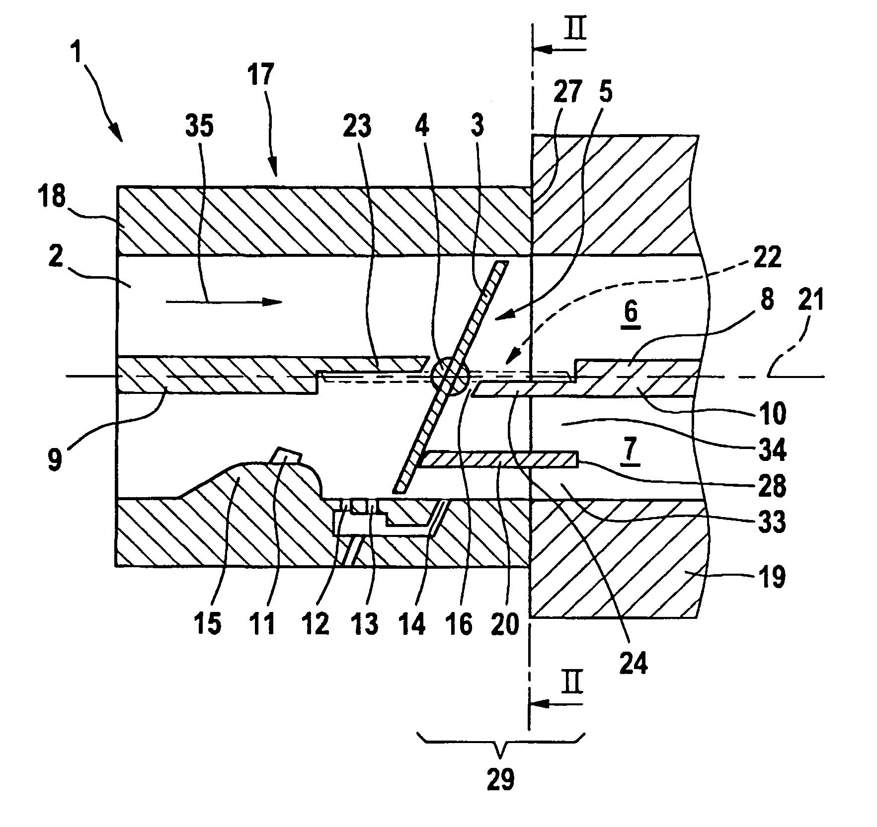
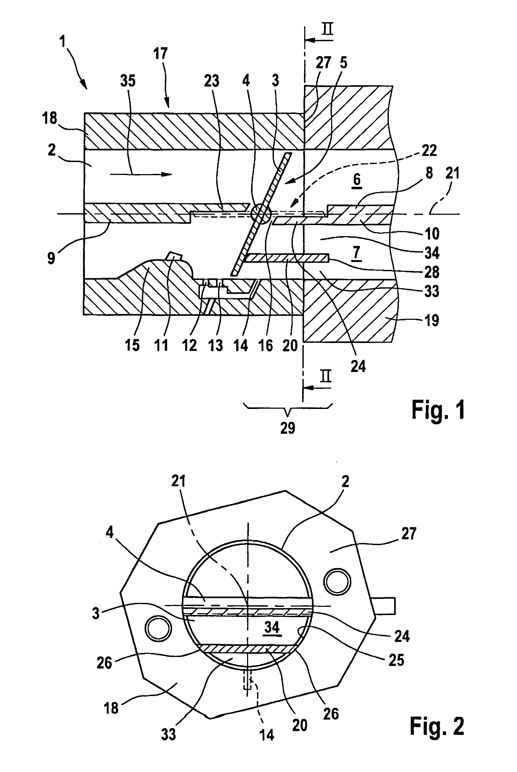
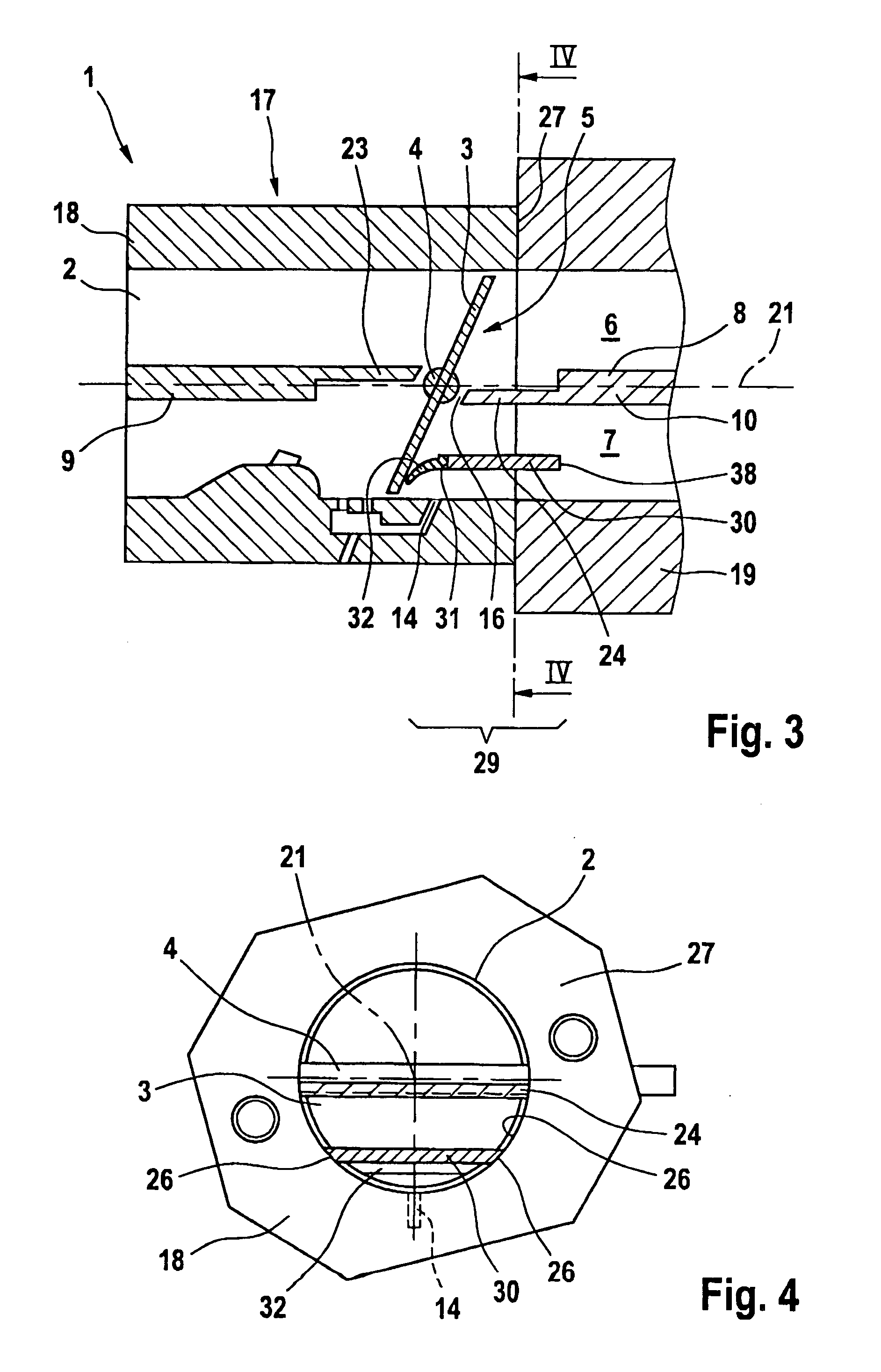
[0016] The intake arrangement 1 shown in FIG. 1 functions to supply combustion air to a two-stroke engine and especially a two-stroke engine in a portable handheld work apparatus such as a motor-driven chain saw, brushcutter or the like. The intake arrangement 1 includes an intake channel 2 wherein a throttle flap 3 is pivotally journalled with a throttle shaft 4. The throttle flap 3 is mounted in a carburetor 17. An air filter (not shown) can be mounted upstream of the carburetor 17 referred to the flow direction 35.

[0017] A flange 19 is arranged downstream of the carburetor 17 and this flange can, for example, be the flange of the two-stroke engine. The flange 19 can, however, also be an intermediate flange. The intake channel 2 is partitioned by a partition wall 8 into an air channel 6 and a mixture channel 7. A partition wall section 9 extends upstream of the throttle flap 3 and a partition wall section 10 extends downstream of the throttle flap 3. Advantageously, the partition...


PUM


Abstract

An intake arrangement (1) for a two-stroke engine includes an intake channel (2) in which a throttle flap (3) is pivotally journalled with a throttle shaft (4). Downstream of the throttle flap (3), a partition wall (8) is mounted on the intake channel (2) and this partition wall partitions the intake channel (2) into an air channel (6) and a mixture channel (7). In the idle position (5) of the throttle flap (3), at least one fuel opening (14) opens into the mixture channel (7) downstream of the throttle flap (3). A connecting opening (16) between the air channel (6) and the mixture channel (7) is provided between the partition wall (8) and the throttle shaft (4) in the idle position (5) of the throttle flap (3). A shield (20, 30) is mounted in the mixture channel (7) between the fuel opening (14) and the connecting opening (16) in order to achieve a good swing performance of the two-stroke engine. The shield reduces the passing of fuel into the air channel and therefore the degree of wetting of the air channel with fuel.

Description

CROSS REFERENCE TO RELATED APPLICATION [0001] This application claims priority of German patent application no. 10 2004 009 310.5, filed Feb. 26, 2004, the entire content of which is incorporated herein by reference. FIELD OF THE INVENTION [0002] The invention relates to an intake arrangement for a two-stroke engine including a two-stroke engine for a portable handheld work apparatus such as a motor-driven chain saw, brushcutter or the like. BACKGROUND OF THE INVENTION [0003] United States patent application publication U.S. 2003 / 0106508 A1 discloses an intake arrangement for a two-stroke engine wherein the intake channel is partitioned by a partition wall into an air channel and a mixture channel downstream of a throttle flap. The partition wall has an opening in the region of the throttle flap and this opening is closed by the throttle flap in the full-load position thereof. In the idle position of the throttle flap, fuel from the mixture channel can reach the air channel via the ...

Claims


Application Information

Patent Timeline
Patent Type & Authority Applications(United States)
IPC IPC(8): F02B25/22F02B25/16F02B75/02F02D9/10F02M9/08F02M35/10F02M35/108
CPCF02B25/22F02B2075/025F02D9/1045F02M9/08Y02T10/146F02M35/10255F02M35/10262F02M35/108F02M35/10196Y02T10/12
Inventor PRAGER, ANDRE
Owner ANDREAS STIHL AG & CO KG
Why Eureka
Try Eureka