Load sensing system for seat

Inactive Publication Date: 2005-09-01
SUBARU CORP +1
View PDF3 Cites 1 Cited by
  • Summary
  • Abstract
  • Description
  • Claims
  • Application Information

AI Technical Summary

Benefits of technology

[0007] The present invention addresses the above disadvantage. Thus, it is an objective of the present invention to provide a load sensing system, which shows a relatively high load sensing accuracy.
[0008] To achieve the objective of the present invention, there is provided a load sensing system, which includes at least one front sensor and at least one rear sensor. The at least one front sensor senses a load, which is applied to a front part of a seat of a vehicle. The at least one rear sensor senses a load, which is applied to a rear part of the seat. A size of an entire load sensing range of each front sensor is smaller than a size of an entire load sensing range of each rear sensor.
[0009] To achieve the objective of the present invention, there is also provided a load sensing system, which includes at least one front sensor and at least one rear sensor. The at least one front sensor senses a load, which is applied to a front part of a seat of a vehicle. The at least one rear sensor senses a load, which is applied to a rear part of the seat. A size of an entire load sensing range of each front sen

Problems solved by technology

However, when a size of the entire load sensing range of each sensor is increased, the load sensing accuracy of the sensor is disadvantageously reduced.
In other words, an occupant determining performance of the occupant sensing ECU for determining the state of the occupant is disadvantageously deteriorated.

Method used


Image

  • Load sensing system for seat
  • Load sensing system for seat
  • Load sensing system for seat

Examples


first embodiment

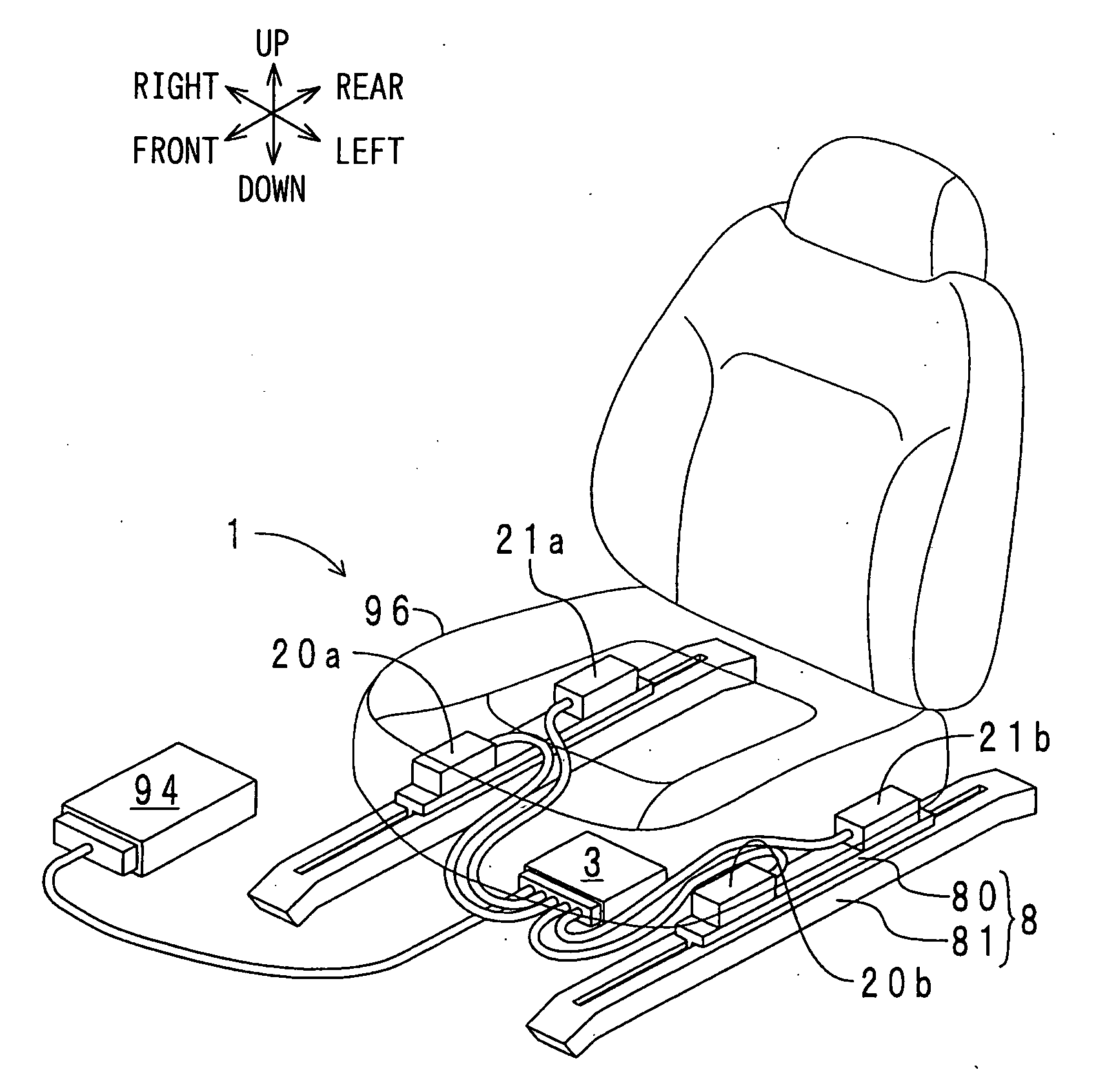
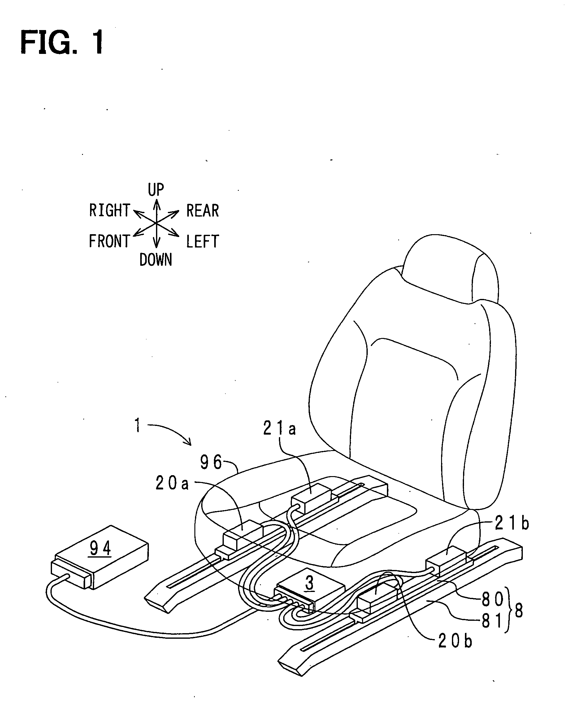
[0019] A load sensing system according to a first embodiment will be described with reference to FIGS. 1 to 5B. With reference to FIG. 1, in the load sensing system 1, two seat rail parts 8 are arranged parallel to each other in a transverse direction (a width direction) of a vehicle. Each seat rail part 8 includes an upper rail 80 and a lower rail 81. The lower rail 81 is secured to a floor (not shown) of a vehicle body. The upper rail 80 is slidable relative to the lower rail 81 in a fore-and-aft direction (a longitudinal direction) of the vehicle. A seat (a front passenger seat) 96 is slidable integrally with the upper rails 80 in the fore-and-aft direction. Two front sensors 20a, 20b and two rear sensors 21a, 21b are placed in a space between a seat frame (not shown) of the seat 96 and the upper rails 80. The front sensors 20a, 20b and the rear sensors 21a, 21b constitute the load sensing system 1 of the present embodiment. The front sensor 20a is vertically opposed to a right f...

second embodiment

[0037] A second embodiment is similar to the first embodiment except that the size of the entire load sensing range of each front sensor and the size of the entire load sensing range of each rear sensor are generally the same. Thus, the following description will be mainly focused on this difference.

[0038]FIG. 6 is a schematic diagram showing the load sensing range of each sensor of the load sensing system of the present embodiment. The components similar to those of FIG. 4 will be indicated by the same numerals. As shown in FIG. 6, the size of the entire load sensing range Ffs of each front sensor 20a, 20b is set to be generally the same as the size of the entire load sensing range Rfs of each rear sensor 21a, 21b. Furthermore, the size of the positive load sensing subrange F(+) of each front sensor 20a, 20b is set to be smaller than the size of the positive load sensing subrange F′(+) of each rear sensor 21a, 21b. Furthermore, the size of the negative load sensing range F′(−) of ...


PUM


Abstract

Each front sensor senses a load, which is applied to a front part of a seat, and each rear sensor senses a load, which is applied to a rear part of the seat. A size of an entire load sensing range of each front sensor is smaller than a size of an entire load sensing range of each rear sensor.

Description

CROSS REFERENCE TO RELATED APPLICATION [0001] This application is based on and incorporates herein by reference Japanese Patent Application No. 2004-36946 filed on Feb. 13, 2004. BACKGROUND OF THE INVENTION [0002] 1. Field of the Invention [0003] The present invention relates to a load sensing system for sensing a load, which is applied to a seat. [0004] 2. Description of Related Art [0005] A load sensing system is used to, for example, determine a state of an occupant who is seating on a vehicle seat. Such a load sensing system includes front and rear sensors (see, for example, Japanese Unexamined Patent Publication No. 2003-14528, which corresponds to U.S. Pat. No. 6,759,604). For instance, the front sensors of the load sensing system may include a pair of front sensors, which are arranged in two front corners of the seat. Also, the rear sensors of the load sensing system may include a pair of rear sensors, which are arranged in two rear corners of the seat. Each front sensor sens...

Claims


Application Information

Patent Timeline
IPC IPC(8): B60N2/00B60N2/90G01G19/52B60R21/01B60R21/015G01G19/12G01G19/414
CPCB60N2/002B60R21/0152B60R21/01516G01G19/4142
Inventor WANAMI, SHINGOGOSHIMA, SATOSHIHANDA, MASAMIKARASAWA, HIDEYUKI
Owner SUBARU CORP
Why Eureka
Try Eureka