Detecting device for detecting the rotation of a motor rotor

a detection device and a technology for motor rotors, which are applied in the field of detecting devices for detecting can solve the problems of large volume of motor devices, inability to offer very precise detections or measurements and the above-discussed prior art generally cannot offer the effect of precise detection of the rotation of motor rotors

Inactive Publication Date: 2005-09-01
EXON SCIENCE INC
View PDF15 Cites 17 Cited by
  • Summary
  • Abstract
  • Description
  • Claims
  • Application Information

AI Technical Summary

Benefits of technology

[0021] A main object of the present invention is to provide a new detecting device for detecting th

Problems solved by technology

Although the rotary encoder method allows a relatively accurate detection of the rotation of the motor, space and cost for the rotary encoder constructed by the rotation slit disk, the phototransistors, etc. are inevitably increased.
However, whether the detecting devices using magnetic effects or those using the optic related theories as above discussed, both have to add extra elements such as the magnetic rotor, windings, and the disk with slits

Method used


Image

  • Detecting device for detecting the rotation of a motor rotor
  • Detecting device for detecting the rotation of a motor rotor
  • Detecting device for detecting the rotation of a motor rotor

Examples


second embodiment

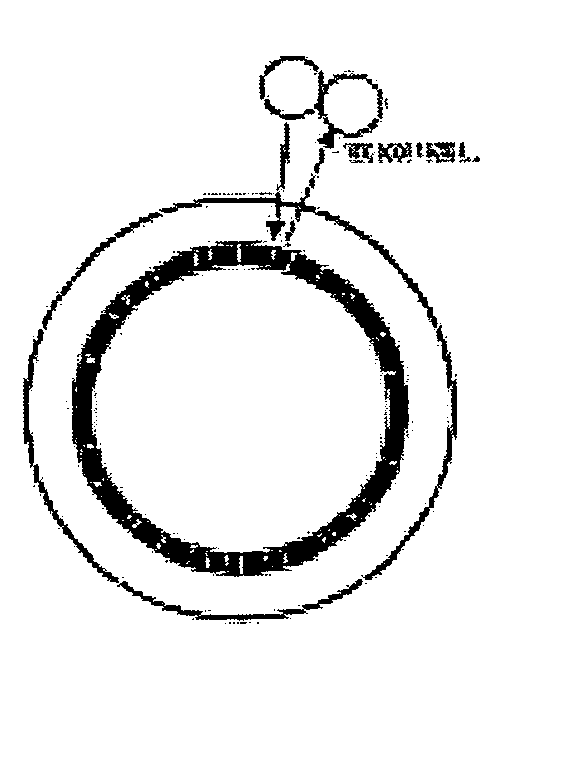
[0081]FIGS. 8 and 24 show the present invention. The identification mark means 6 of the detecting device 5 may include a plurality of convex portions 612 formed on the outer surface of the cylindrical shoulder 42.

[0082] The convex portions 612 are arranged in a way that the distances traveled by first light beams emitted by the light source, which reach and are reflected by the convex portions 612, are different from the distances traveled by second light beams emitted by the light source 7, which reach and are reflected by separating portions (not labeled) between adjacent convex portions 612, which are lower compared with the convex portions 612.

first embodiment

[0083] The traveling distance distinction between an according first reflected light beam and an according second reflected light beam can be a predetermined multiple of the wavelength of the light beams by the light source 7, which is substantially the same with that of the

[0084] The arrangement of the convex portions 612 and the separating portions therebetween should satisfy substantially the same requirements or rules as those of the first embodiment as discussed above. Hence, detailed descriptions are omitted herewith.

[0085] The identification mark means 6 also can be a colored means 620 as shown in FIGS. 9 and 10 respectively.

third embodiment

[0086] In a third embodiment in accordance with the present invention as shown in FIGS. 9 and 25, the colored means 620 can be consisted of a series of consecutive colored portions 622 whose color varies from light to dark. The specific color of the colored portions 622 may be green or yellow, or other appropriate color as desired.

[0087] The arrangement of the colored means 620 should ensure that the sensor 8 can detect the rotation of the motor rotor 4 by reading the changes of the light beams firstly emitted by the light source 7 and then reflected respectively by corresponding adjacent colored portions 622 of the colored means 620.

[0088] For example, the colored portions 622 thereof are arranged so that the reflectivity thereof can vary according to the requirements of the sensor 8. The colored portions 622 can alternatively be arranged so that the wavelengths of the reflected light beams by adjacent colored portions 622 can vary according to the requirements of the sensor 8.


PUM


Abstract

A detecting device for detecting the rotation of a motor rotor includes a light source, an identification mark means positioned around the motor rotor, and a sensor for detecting the light beams emitted by the light source and coming from the identification mark means. The identification mark means can be positioned on a cylindrical shoulder formed around the rotor thereby rotating with the motor rotor synchronously. The light source can emit light beams at two different wavelengths, and the sensor can thus receive and read the light beams with the two different wavelengths respectively reflected from the identification mark means thereby producing according binary code signals carrying more detailed information thereof, whereby the detecting device can achieve very precise detection of the rotation of the motor rotor.

Description

TECHNICAL FIELD [0001] The present invention relates to a detecting device for detecting the rotation of a motor rotor, especially a detecting device which can achieve precise detection of the rotation of the motor rotor. DESCRIPTION OF RELATED ARTS [0002] Various methods and devices have been employed to detect the rotation of a rotor of a motor. In fact, the methods and / or devices which are used for measuring or detecting a rotating shaft can also be adopted for detecting the rotor of a motor. [0003] Traditionally, rotation sensors are adopted for detecting the rotation of a rotating shaft as above-mentioned. U.S. Pat. No. 4,030,066 gives a gyro which can be installed concentrically around the shaft connected with the steering wheel so that the turning angle of the wheel can be judged by detecting the turning angle of the shaft. There are also various devices except the gyro mechanism to detect the turning angle of a rotating shaft, such as a resonant rotation rate sensor which em...

Claims


Application Information

Patent Timeline
IPC IPC(8): G01B11/26G01D5/26G01D5/34G01D5/347G01D5/36H02K29/10
CPCG01D5/34G01D5/366G01D5/363G01D5/3473A01G9/026A01G24/00A01G24/20B42D15/02
Inventor SU, WEN-WEI
Owner EXON SCIENCE INC
Why Eureka
Try Eureka