Low flow valve improvement

a low-flow valve and improvement technology, applied in the field of irrigation valves, can solve the problems of increased manufacturing cost and difficulty, inefficient or faulty valve operation,

Active Publication Date: 2005-09-01
TORO CO THE
View PDF6 Cites 13 Cited by
  • Summary
  • Abstract
  • Description
  • Claims
  • Application Information

AI Technical Summary

Benefits of technology

[0010] It is a further object of the present invention to provide an improved valve that continues to close at low water flows over an extended period of time.

Problems solved by technology

While this method prevents diaphragm extrusion, it presents increased manufacturing expense and difficulties by presenting another plastic part to design and injection mold.
Further, the manufacturing conditions for both the closure member and the insert must be highly controlled and precise, otherwise the insert will fit poorly within the closure member, risking inefficient or faulty valve operation.

Method used


Image

  • Low flow valve improvement
  • Low flow valve improvement
  • Low flow valve improvement

Examples


Embodiment Construction

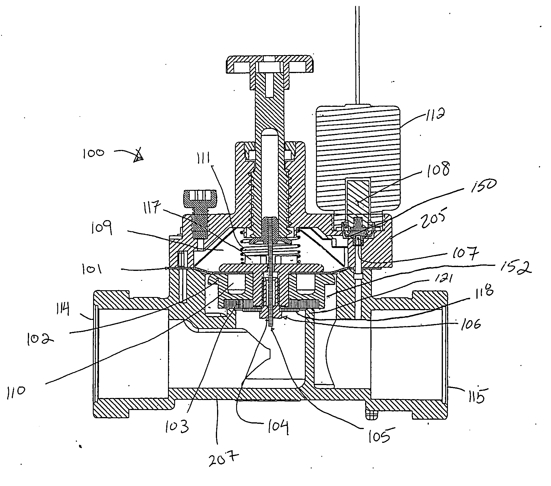
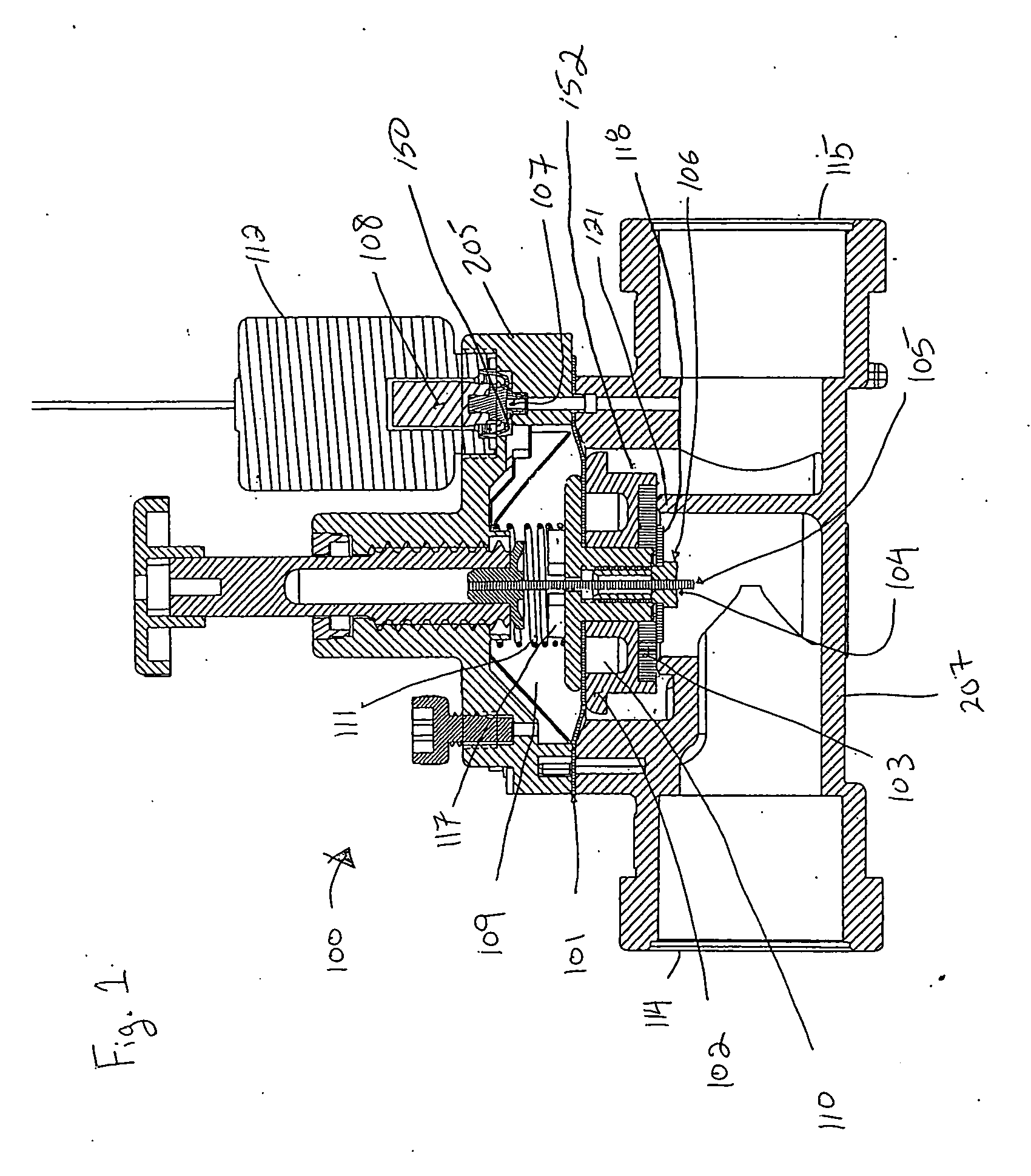
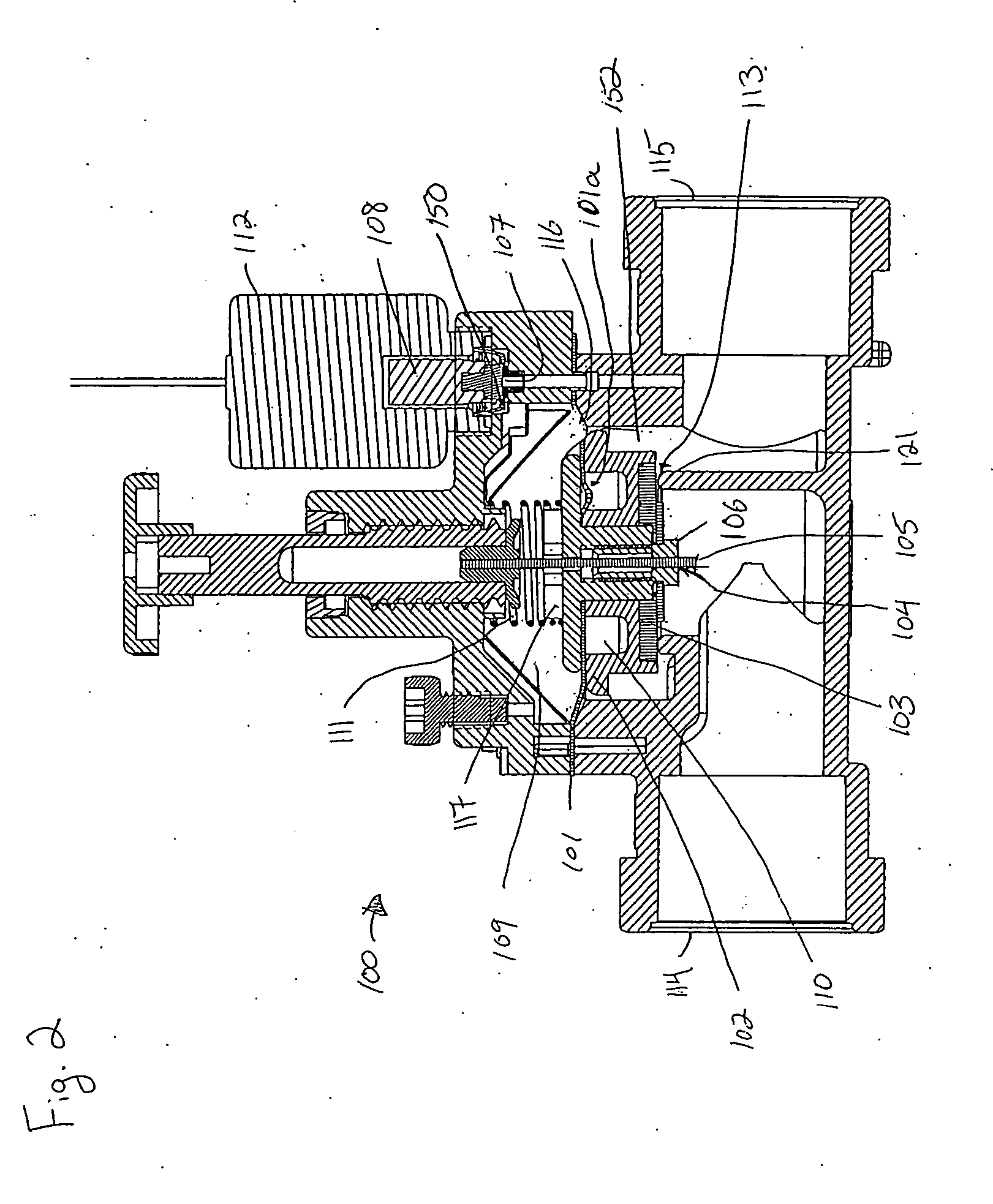
[0018]FIGS. 1 and 2 illustrate a prior art irrigation valve 100 in the closed position. This irrigation valve 100 includes a water inlet port 114, a water outlet port 115, and a guide washer 102 that includes a sealing surface 103. Typically the sealing surface 103 is made from a rubber or other resilient material.

[0019] The valve is actuated by a solenoid 112 that is connected to a solenoid plunger 108 which controls the opening and closing of a discharge port 107. In the closed position, the solenoid plunger 108 blocks a passage 150 that otherwise connects a diaphragm chamber 109 (located above a diaphragm 101) to the discharge port 107 and to the valve water outlet port 115.

[0020] The valve assembly 120 seals off the diaphragm chamber 109 from the lower portion of the valve. As seen in FIG. 5, the valve assembly 120 is made up of a diaphragm retaining cap 117 which sits over a diaphragm 101. Beneath the diaphragm sits a guide washer 102 having an inner circular channel 110. Ret...


PUM


Abstract

The present invention illustrates an irrigation valve that operates at low flows by providing a guide washer of the valve assembly that prevents diaphragm extrusion. Specifically, the circular channel area of a guide washer of the valve includes spoke-like fins. These fins keep the diaphragm from extruding into the open channel over time, while allowing for easy guide washer manufacturing.

Description

FIELD OF THE INVENTION [0001] This invention relates to an irrigation valve for controlling the flow of water through piping of an irrigation system. More particularly, this invention relates to an irrigation valve with improved operation at low water flows. BACKGROUND OF THE INVENTION [0002] Flow control valves are a well known and integral part of most irrigation systems. A typical example can be seen in U.S. Pat. No. 6,394,413 to Lohde, et al, herein incorporated by reference. [0003] These valves control the flow of water through an upstream pipe and thereby turn sprinklers fed by the pipe on and off. Such valves are usually remotely actuated by control signals sent from an automated irrigation controller. Often, these control signals are electric impulses sent from the controller to a solenoid in the valve which ultimately controls whether the valve is open or closed. [0004] Pilot-activated diaphragm-operated valves for use in irrigation systems are well known. One example can b...

Claims


Application Information

Patent Timeline
Patent Type & Authority Applications(United States)
IPC IPC(8): F16K31/40
CPCF16K31/402
Inventor LEE, HYOK
Owner TORO CO THE
Why Eureka
Try Eureka