Poppet valve device and electronic controlled fuel injection apparatus equipped with the device

a technology of electronic control and poppet valve, which is applied in the direction of valve operating means/release devices, machines/engines, non-mechanical valves, etc., can solve the problems of inevitably limited axial passages, cracked parts of said limited radial thickness, etc., and achieve the effect of preventing the occurrence of bouncing increasing the sliding friction of the poppet valve body

Active Publication Date: 2005-09-01
MITSUBISHI HEAVY IND ENGINE & TURBOCHARGER LTD
View PDF3 Cites 5 Cited by
  • Summary
  • Abstract
  • Description
  • Claims
  • Application Information

AI Technical Summary

Benefits of technology

[0015] The present invention was made in light of the problems as above described, and the object is to provide a poppet valve device with which the occurrence of a crack in the passage exposed to high-pressure liquid in the valve device, occurrence of cavitation erosion in the poppet valve body and valve seat member of the valve device, increase in sliding friction of the poppet valve body, and the occurrence of bouncing of the poppet valve body can be prevented.

Problems solved by technology

Conventionally, one axial passage has been provided in the valve seat member, and the radial thickness between periphery of the trough-hole (hereafter referred to the sliding surface) and the periphery of the axial passage is inevitably limited for space limitation, and when the valve device was used for high-pressure injection apparatus, the part of said limited radial thickness cracked.

Method used


Image

  • Poppet valve device and electronic controlled fuel injection apparatus equipped with the device
  • Poppet valve device and electronic controlled fuel injection apparatus equipped with the device
  • Poppet valve device and electronic controlled fuel injection apparatus equipped with the device

Examples


first embodiment

The First Embodiment

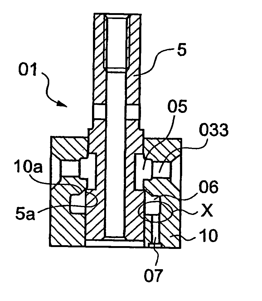
[0048]FIG. 1(A) is a sectional view of a first embodiment of the poppet valve device according to the present invention, FIG. 1(B) is an enlarged detail of part X in FIG. 1(A) and shown in comparison with the case of prior art, and FIG. 1(C) is a section along line Y-Y in FIG. 1(B) and the case of present invention is compared with the case of prior art.

[0049] In FIG. 1(A), a poppet valve device 01 consists of a poppet valve body 5 and valve seat member 10. Reference numeral 05 is a low-pressure room, 06 is a high-pressure room, 07 is an axial passage connecting to the high-pressure room 06, and 033 are radial passages connecting to the low-pressure room 05. These reference numerals are the same as those of the poppet valve device in FIG. 7. Arrows in FIG. 1(B) show the state fuel pressure is exerting in the high-pressure room 06.

[0050] In FIG. 1(C), the case the axial passage 07 consists of two passages each having diameter d1 is compared with the case the axi...

second embodiment

The Second Embodiment

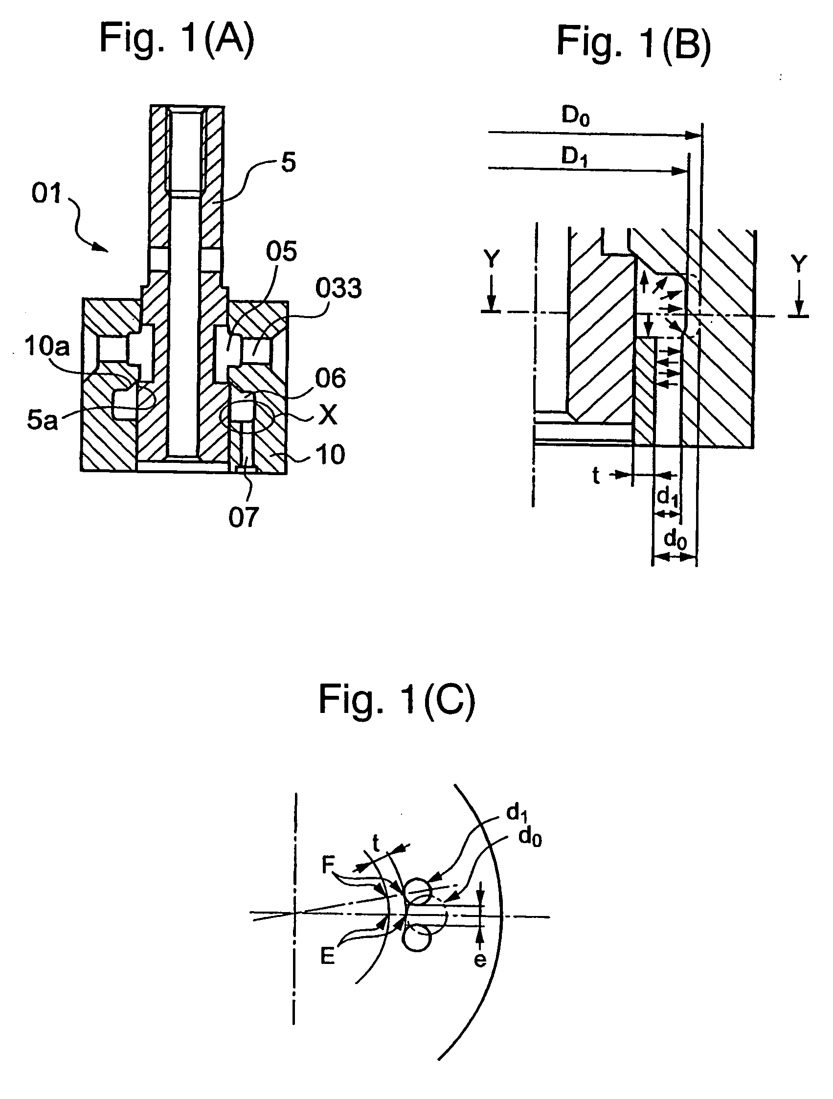
[0053]FIG. 2 is a sectional view of a second embodiment of the poppet valve device according to the present invention. In the drawing, two axial passages 07 of right and left are provided, other than this point the poppet valve device of FIG. 2 is configured similar to that of FIG. (A), and the same reference numerals are used for components and function parts same or similar to those of FIG. 1(A). In this case, as high-pressure liquid flows into the high-pressure room 06 through the right and left axial passages 07 at the same time, the poppet valve body 5 experiences pressure from the high-pressure liquid flow at the same time from right and left, and the poppet valve body 5 does not experience a side thrust as does in the case only one axial passage is provided.

[0054] Therefore, the increase of friction by a side thrust when the poppet valve body slides in the valve seat member 10 can be prevented.

[0055] When the valve opens, the liquid in the high-pressure...

third embodiment

The Third Embodiment

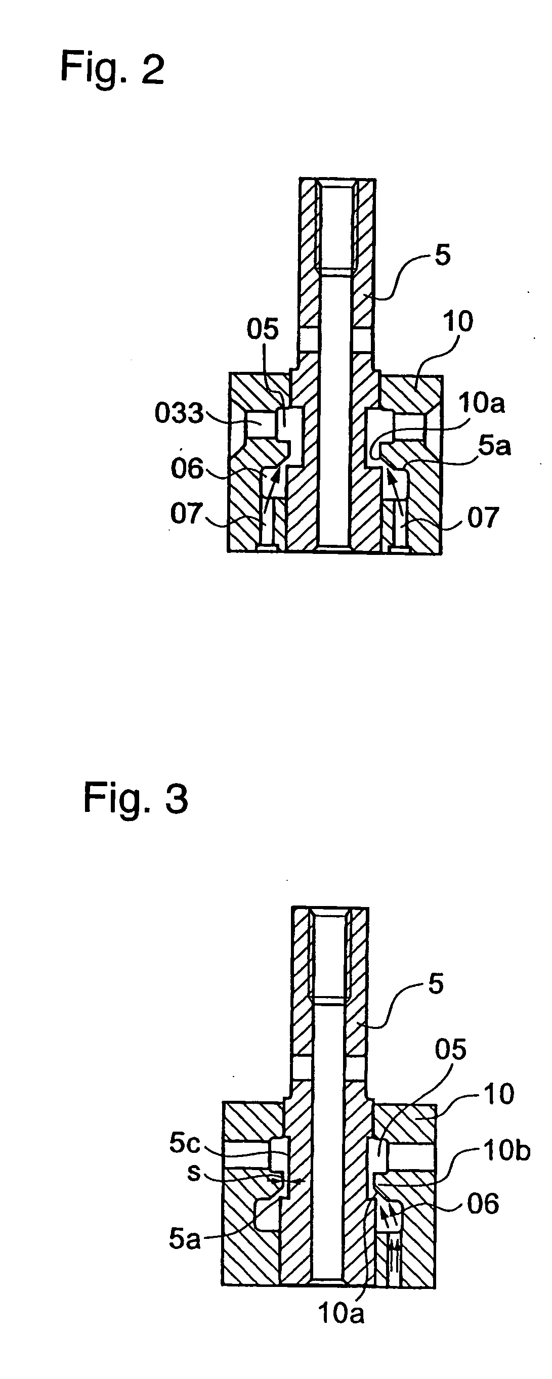
[0057]FIG. 3 is a sectional view of a third embodiment of the poppet valve device according to the present invention, and the same reference numerals are used for components and function parts same or similar to those of FIG. 1(A). A point different from the poppet valve device of FIG. 1(A) is that the width “s” of the annular gap between the periphery 5c of the middle part of the poppet valve body 5 and the inside perimeter of the annular projection 10b of the valve seat member 10 for forming the valve seat 10a is narrowed to throttle liquid flow.

[0058] When the seat face 5a of the poppet valve body 5 departs from the seat 10a of the valve seat member 10 and a gap is developed between the seat faces, high-pressure liquid flows out from the high-pressure room 06 to the low-pressure room 05 passing through the gap between the seat faces and further passing through said annular gap of width “s”. When the annular gap of width “s” is narrowed, the flow through the a...


PUM


Abstract

The poppet valve device is composed such that a plurality of axial passages of substantially the same diameter and length communicating to the high-pressure room formed inside the valve seat member between the poppet valve body and the valve seat member are provided in the valve seat member, the passages being located adjacent to each other, or passages being located axially symmetrically, and the annular gap formed between the periphery of the poppet valve body and the inner perimeter of the projecting part on which the valve seat face of the valve seat member is formed is narrow to restrict liquid flow through the annular gap. The electronic controlled fuel injection apparatus equipped with the poppet valve device is composed such that the lower end part of the poppet valve body and the bottom of the valve device accommodating part of the fuel injection apparatus are formed to restrict the flow of the fuel between the lower end of the poppet valve body and the bottom of the valve device accommodation part to the central hollow of the poppet valve body, whereby the occurrence of bouncing is prevented.

Description

BACKGROUND OF THE INVENTION [0001] 1. Field of the Invention [0002] The present invention relates to a poppet valve device for performing opening and closing of a high-pressure liquid passage, specifically to a poppet valve device to control the injection timing of the electronic controlled fuel injection apparatus for an internal combustion engine. [0003] 2. Description of the Related Art [0004] In diesel engines, electronic controlled fuel injection apparatuses are widely used recently as effective means for reducing atmospheric pollutant such as NOx(nitrogen oxides) and HC(hydrocarbons)(for example, see Japanese Laid-Open Patent Application Nos 2001-248479 and 2002-98024). [0005] A poppet valve device driven by an electromagnetic valve device is used in each of these apparatuses for opening and closing the fuel passage in the apparatus. [0006]FIG. 6 represents an example of a unit injector type electronic controlled fuel injection apparatus for diesel engine. The unit injector li...

Claims


Application Information

Patent Timeline
Patent Type & Authority Applications(United States)
IPC IPC(8): F02M51/06F02M57/02F02M59/36F02M51/00F02M63/00F16K11/07F16K31/02F16K31/06F16K31/12F16K31/36F16K47/04
CPCF02M57/02F02M59/366F02M63/0015F02M63/0031F16K47/04F02M2200/304F16K11/0716F16K31/061F16K31/0624F02M2200/04Y10T137/86759
Inventor OGAWA, HISAOKANEKO, TAKASHI
Owner MITSUBISHI HEAVY IND ENGINE & TURBOCHARGER LTD
Why Eureka
Try Eureka