
Ear insert for hearing aids

Inactive Publication Date: 2005-09-01
SIVANTOS PTE LTD
View PDF5 Cites 37 Cited by
  • Summary
  • Abstract
  • Description
  • Claims
  • Application Information

AI Technical Summary

Benefits of technology

[0011] An object of the present invention is to provide an ear insert which has the advantages of an exchangeable earpiece and features improved acoustic properties.
[0012] In accordance with the invention this object is achieved by an ear insert for a hearing system with a shaped part (also referred to as a molded padding) which can be fitted into the auditory canal of the ear and an earpiece which is arranged in the shaped part so that it can be removed, to conduct the sound to the ear, with a sound outlet formed in accordance with acoustic conditions being embodied between the earpiece and the side of the shaped part, which in the state in which the ear insert is placed in the auditory canal, is facing the eardrum The sound outlet is embodied in the capsule. This means that although the capsule for the earpiece is somewhat more expensive to manufacture, the shaped part by contrast is cheaper to manufacture. Preferably the sound outlet is embodied funnel-shaped. Ideally the sound outlet is in the form of an exponential horn which produces optimum impedance matching. On the side of the shaped part facing away from the eardrum a cover is fitted to which a cutout in the shaped part in which the capsule is placed can be closed off. This enables the capsule to be formed relatively simply without any fear of an unwanted shaking out of the earpiece from the ear insert. Optionally the cover can be designed to be removable from the shaped part, which makes the device easier to assemble in some cases.
[0014] For high-tone hearing aids in particular this produces an improved acoustic impedance matching.
[0015] The sound outlet can be embodied in the shaped part. In this case a capsule or an adapter which allows the earpiece to be easily exchanged, can be produced at very low cost.
[0017] The shaped part can further be an earmold. This enables a precise individual adaptation to an auditory canal to be achieved.
[0018] The earpiece can be contacted via this cover. It this case it is useful for spring contacts to be used for making contact with the earpiece to be arranged on the capsule and / or the cover. This minimizes the installation effort involved in fitting or exchanging an earpiece in the ear insert.

Problems solved by technology

High-tone hearing aids with a largely open supply are very adversely affected both by sound radiation from the vent (the opening) and also by the attenuation properties of the sound tube for high frequencies.
The disadvantage of this layout however is that to service the device if the earpiece fails or becomes contaminated in the otoplastic, said otoplastic has to be replaced, which involves considerable effort and costs, since each otoplastic is formed individually.
However this construction is too large in its design for normal use of BtEs.

Method used


Image

  • Ear insert for hearing aids
  • Ear insert for hearing aids
  • Ear insert for hearing aids

Examples


first embodiment

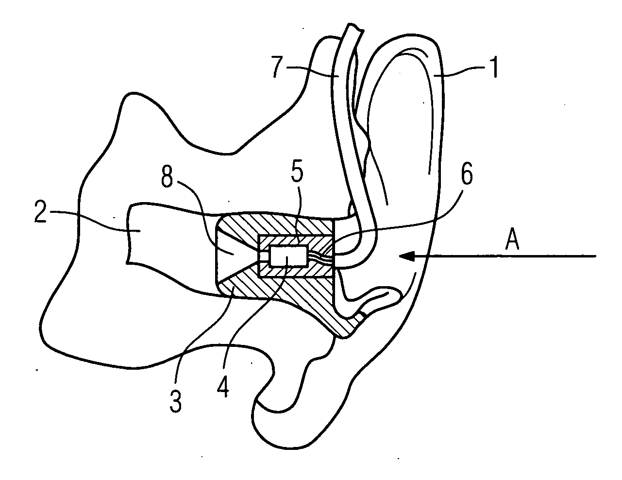
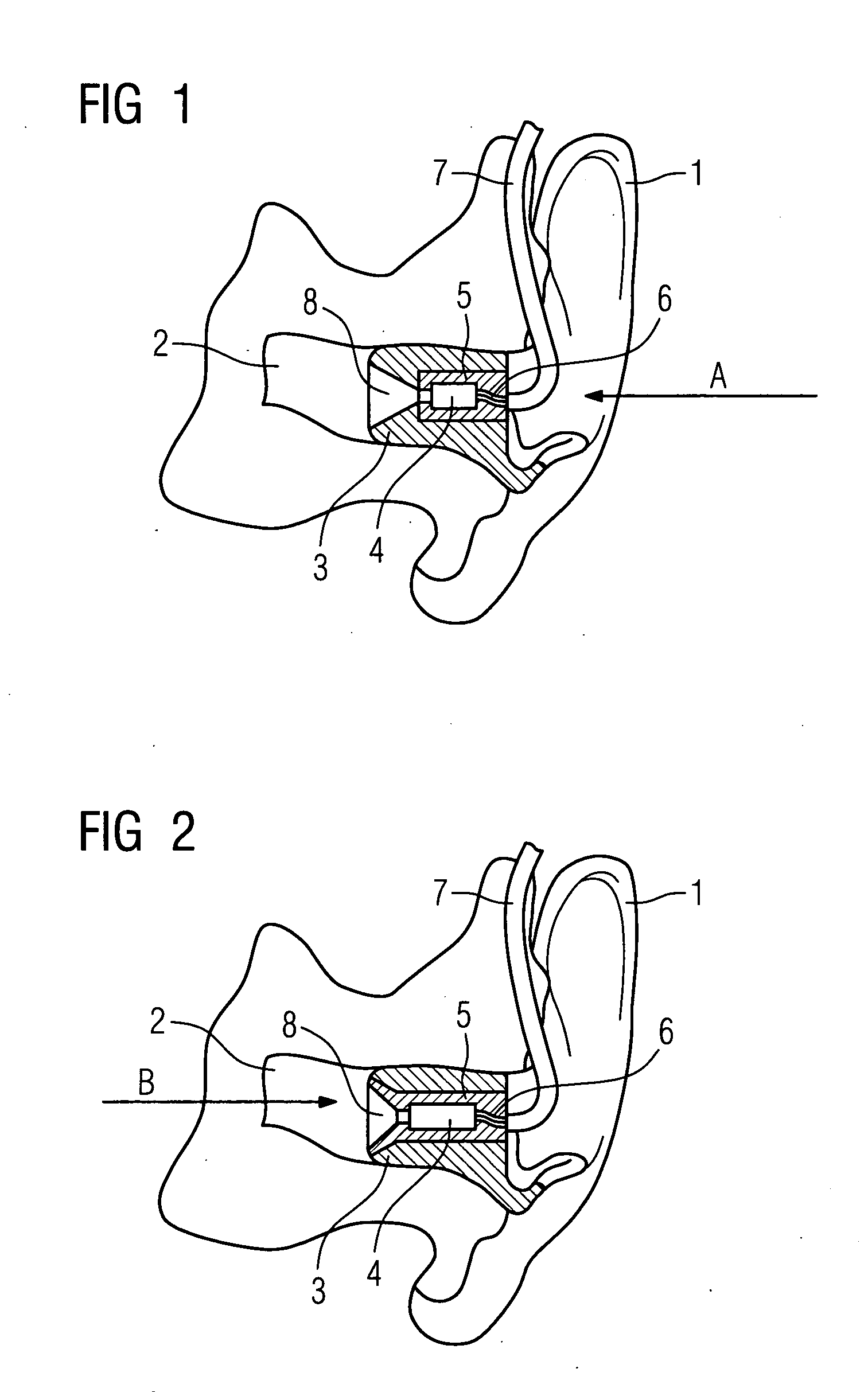
[0028] In this first embodiment of the capsule or the adapter 5 is inserted from outside in the direction of the arrow A into the otoplastic. This enables it to be taken out of the otoplastic 3 without the latter having to be removed from the auditory canal The adapter 5 is fixed in the otoplastic 3 with a corresponding opposing element of the plug-in, screw, bayonet or jack connector.

[0029] On the side facing the ear drum the otoplastic 3 features a funnel-shaped sound outlet 8 indicated which can also be referred to as the sound channel. This sound outlet 8 can also be embodied so that it is similar to a horn and in particular has the form of an exponential horn. The acoustic engineer can adapt the form of the sound outlet to the acoustic circumstances, e.g. residual volume in the auditory canal, frequency spectrum of the earpiece supply, impedance matching etc, as required

[0030]FIG. 2 shows the second embodiment of the inventive ear insert. With this embodiment only the adapter ...

second embodiment

[0031] With the second embodiment in accordance with FIG. 2 the adapter 5 is inserted or placed in the direction of the arrow B, i.e. from the side of the otoplastic 3 facing the ear drum. In this case the funnel-shaped sound outlet 8 is incorporated into the capsule or the adapter 5. In its external contours of the adapter 5 is slightly conical in shape so that it is prevented from shaking free outwards from the otoplastic 3 The adapter 5 can also be designed to have a strictly cylindrical outer contour as shown in FIG 1. In this case it is advisable to provide a corresponding stop so that the adapter 5 cannot unintentionally be shaken out. Alternatively the adapter 5 can also be spherical in design.

third embodiment

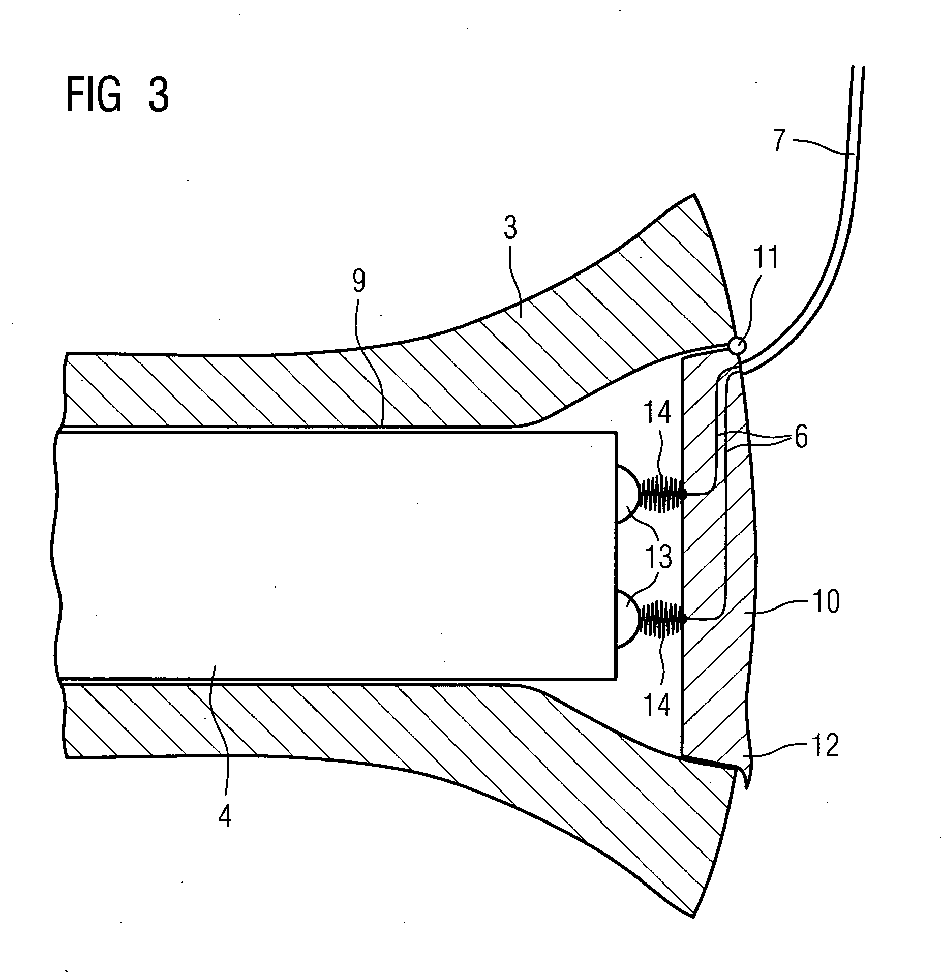
[0032]FIG. 3 shows the present invention. This third embodiment can be combined with both the first and the second embodiment. A cutout 9 is embodied in the otoplastic 3 into which the earpiece 4 is inserted The cutout is closed off by a cover 10. The cover 10 for its part is attached by a hinge 11 to the otoplastic 3 and has a handle 12 for opening it. The connecting leads 6 are in this case routed through the cover 10. The flexible lead 7 is routed in its turn to the BtE. Like a battery, the earpiece 4 has two contacts 13. Spring contacts 14 which are attached to the cover 10 make the electrical contact between the contact points 13 and the leads 6 when at the cover 10 is in its closed state. This enables the earpiece 4 to be replaced with just a few operations.

[0033] Instead of the earpiece 4, an adapter or a capsule into which an earpiece is integrated could be inserted into the cutout 9 and contact established when the cover 10 is closed.

[0034] In accordance with the embodimen...


PUM


Abstract

Active otoplastics (3) with integrated earpieces (4) are to be acoustically optimized. There is provision here for forming a sound outlet (8) into the otoplastic in accordance with acoustic conditions. If the sound outlet (8) has the form of an exponential horn, this results in advantages for supply of high tones. The earpiece (4) can be secured with the aid of an adapter (5) into the otoplastic (3) so that it can be exchanged.

Description

CROSS REFERENCE TO RELATED APPLICATIONS [0001] This application claims priority to the German application No. 10 2004 009 268.0, filed Feb. 26, 2004 which is incorporated by reference herein in its entirety. FIELD OF INVENTION [0002] The present invention relates to an ear insert for a hearing system, especially a hearing aid, with a shaped part which can be pressed into the auditory canal of the ear, a capsule which is arranged so that it can be removed from the shaped part and an ear piece to supply sound to the ear which is arranged in the capsule. BACKGROUND OF INVENTION [0003] High-tone hearing aids with a largely open supply are very adversely affected both by sound radiation from the vent (the opening) and also by the attenuation properties of the sound tube for high frequencies. Therefore it is of great benefit to relocate the earpiece under such circumstances. In this case the earpiece is fixed or molded into an otoplastic or an earmold. The earpiece is connected via a cabl...

Claims


Application Information

Patent Timeline
IPC IPC(8): H04R25/00H04R25/02
CPCH04R25/02H04R25/652H04R25/604H04R25/48
Inventor ACH-KOWALEWSKI, GERHARDKLEMENZ, HARALDNIEDERDRANK, TORSTEN
Owner SIVANTOS PTE LTD
Learn More