Optical switching apparatus and optical switching method

a technology of optical switching and optical switching device, which is applied in the field of optical communication devices, can solve the problems of optical transmission interruption, maintenance is often required, and the loss between the channels might be even larger for a high-capacity switch, and achieve the effect of improving the compensation function for loss and loss differential

Inactive Publication Date: 2005-09-01
HITACHI LTD
View PDF8 Cites 0 Cited by
  • Summary
  • Abstract
  • Description
  • Claims
  • Application Information

AI Technical Summary

Benefits of technology

[0013] It is an objective of certain embodiments of the present invention to provide an optical switching apparatus with improved compensat

Problems solved by technology

These losses between the channels might be even larger for a high-capacity switch including a multi-stage combination of the commercially available low-capacity optical switches.
Thus, maintenance is often required for those transmission lines between the stages, and the optical transmission is interrupted during the maintenance.
Further, the interruption may also occur when the high-capacity optical switch is under the normal operation.
A high-capacity switching apparatus, in which optical amplifiers are placed inside or after optical switches, such as the ones disclosed in References A and C, often causes sensitivity degradation of the optical parts on the reception side due to light surges caused by the above described interruption of light.
Since the spontaneous emission

Method used


Image

  • Optical switching apparatus and optical switching method
  • Optical switching apparatus and optical switching method
  • Optical switching apparatus and optical switching method

Examples


Embodiment Construction

[0026] The optical switching apparatus of the present invention and methods for using this apparatus will be described in detail using the drawings.

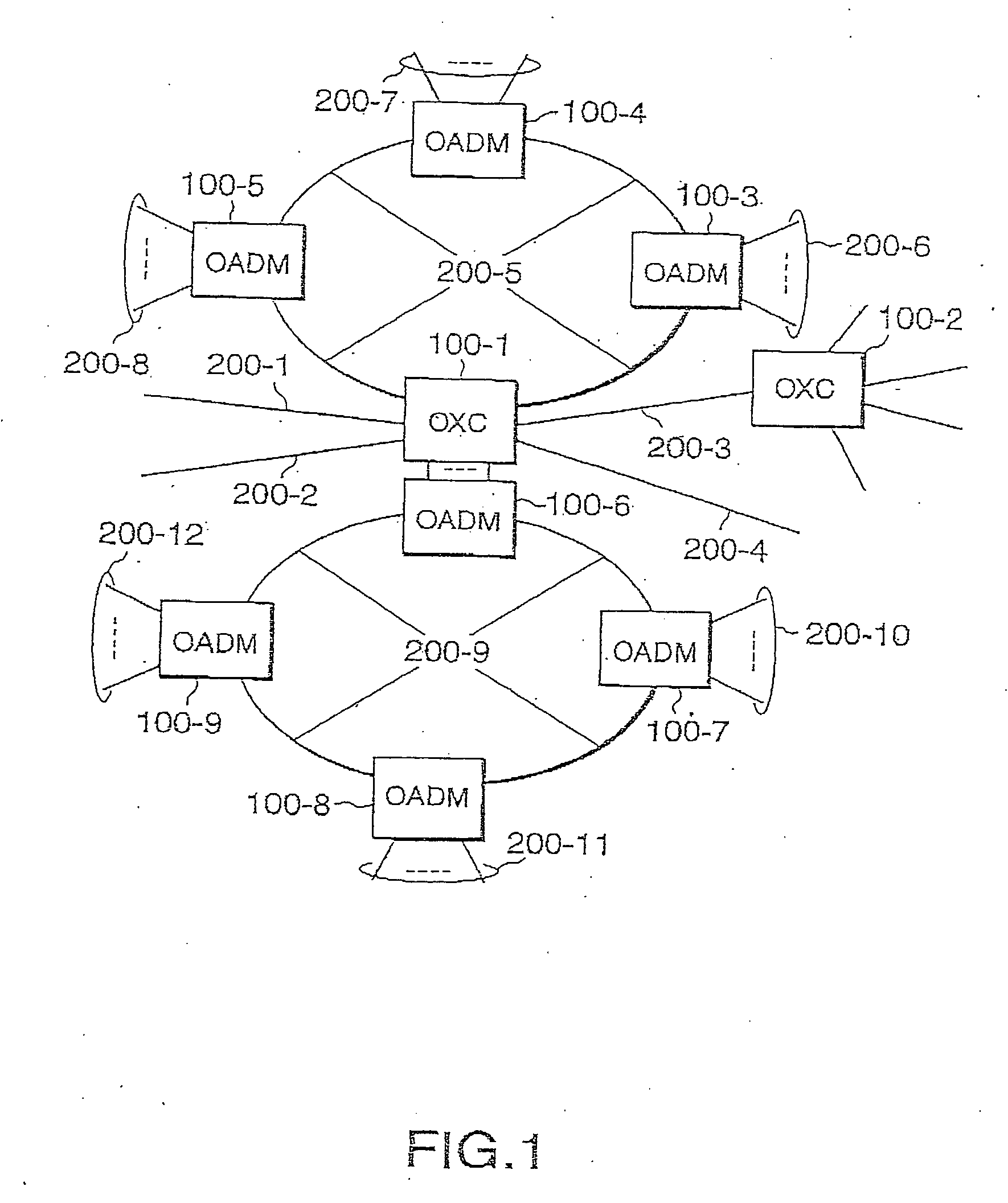
[0027]FIG. 1 is a schematic diagram of a network, which illustrates an example of configuration of a communication network wherein the optical switching apparatuses of the present invention are used. The optical switching apparatuses or the OADM'S 100-1˜100-9 are interconnected with optical fibers 200-1˜200-12 to form a communication network. Specific types of the optical switching apparatuses include optical cross-connects or OXC, 100-1, 100-2, which switch, multiplex and output the multiplexed optical signals received from each of the input optical fibers, 200-1˜200-5 to the output optical fibers. Other switching apparatuses include the optical add-drop multiplexing apparatuses, OADM 100-3˜100-9, which separate or insert the optical signals needed for the OADMs connected to the other OADMs from the multiplexed optical signals received...


PUM


Abstract

An optical switching apparatus includes an optical switch having a plurality of input ports and output ports, optical amplifiers, monitor circuits, optical amplifiers monitor circuits, and a controller that controls the optical switch. The optical amplifiers are connected to the input ports of the optical switch. The monitor circuits are connected to the output ports of the optical switch. The controller selects one of the plurality of the monitor circuits based on predetermined rules to obtains the loss at the output ports and/or the differential loss between the channels of the optical switch. The controller further selects one of the optical amplifiers based on the configuration of the optical switch to compensate the loss and the differential loss among the different channels of the optical switch by pre-amplifying the optical signals before they reach the input ports of the optical switch.

Description

BACKGROUND OF THE INVENTION [0001] 1. Field of the Invention [0002] The present invention relates to an optical communication device and methods of using this device. In particular, the present invention relates to an optical switching apparatus suitable for switching and outputting optical signals received from a plurality of optical transmission lines to other optical transmission lines, and methods for using this apparatus. [0003] 2. Prior Art of the Invention [0004] To handle the sudden increase in data traffic through the Internet, etc. and the quickly growing demands for multimedia communication of images, sound and data, much progress has been made to increase the speed and the capacity of the transmission lines and telecommunication network nodes. To achieve a higher transmission speed, optical communication devices and optical fiber transmission lines are generally used to transmit signals between telecommunication network nodes. [0005] In recent years, to handle the ever i...

Claims


Application Information

Patent Timeline
IPC IPC(8): H04B10/07H04B10/27H04B10/29H04B10/293H04B10/564H04B10/572H04Q11/00
CPCH04Q11/0005H04Q2011/0016H04Q2011/0083H04Q2011/0039H04Q2011/0049H04Q2011/0024
Inventor FUKASHIRO, YASUYUKIHIRAI, TOORU
Owner HITACHI LTD
Why Eureka
Try Eureka