Image forming apparatus

a technology of forming apparatus and forming roller, which is applied in the direction of electrographic process apparatus, instruments, optics, etc., can solve the problems of inability to use magnetic force to supply the development roller, prior art such as the above described, and achieve the effect of high quality

Inactive Publication Date: 2005-09-01
CANON KK
View PDF11 Cites 15 Cited by
  • Summary
  • Abstract
  • Description
  • Claims
  • Application Information

AI Technical Summary

Benefits of technology

[0025] The primary object of the present invention is to provide an image forming apparatus capable of consistently forming high quality images.
[0026] Another object of the present invention is to provide an image forming apparatus which does not change in image density even if its image bearing...

Problems solved by technology

However, in some situations, when the leading edge of a recording medium begins to enter the fixing apparatus, the trailing edge of the recording medium is still in the middle of the development process.
In the non...

Method used


Image

  • Image forming apparatus
  • Image forming apparatus
  • Image forming apparatus

Examples


embodiment 1

[General Structure and Operation of Image Forming Apparatus]

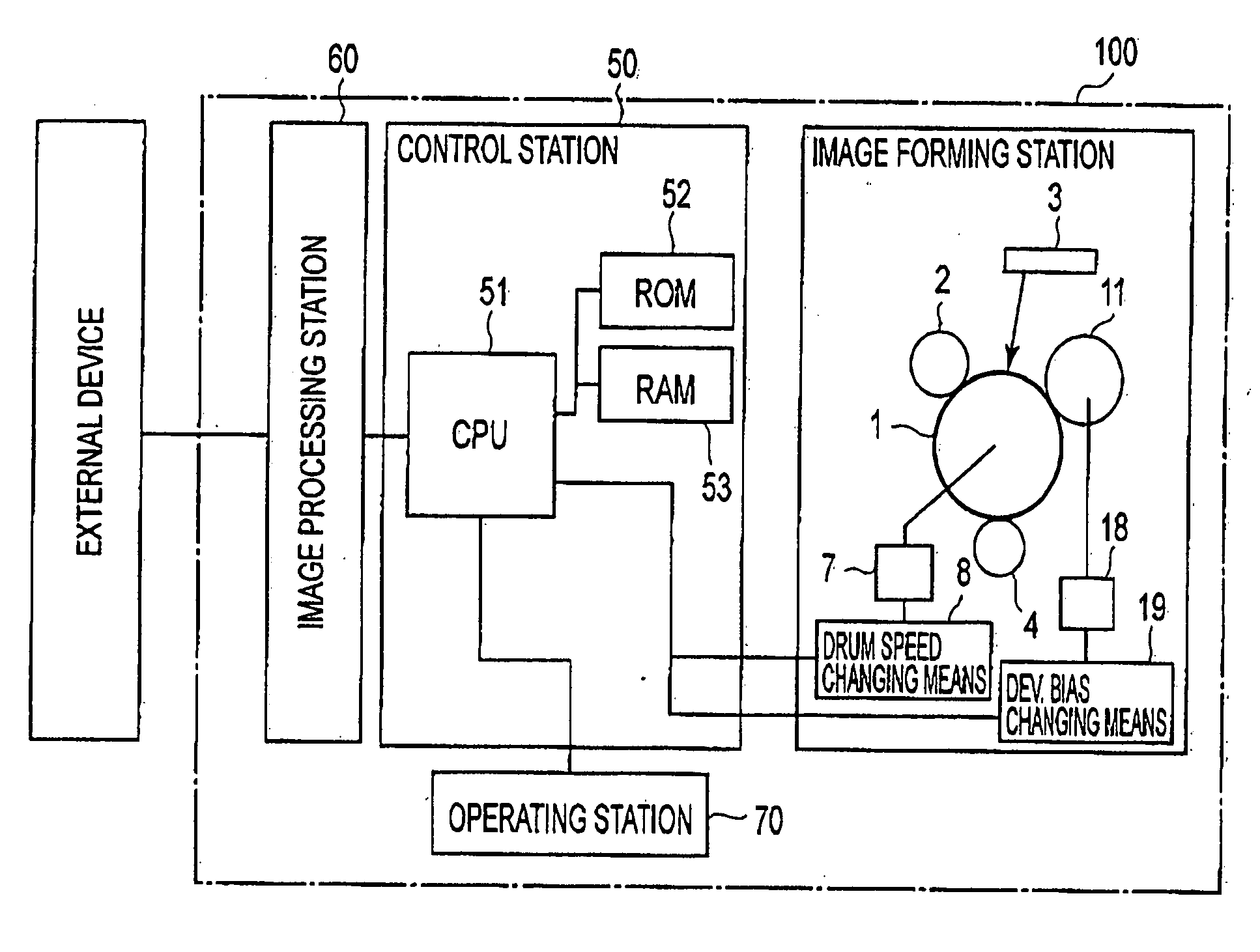
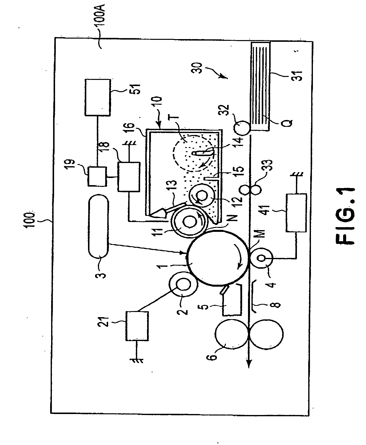
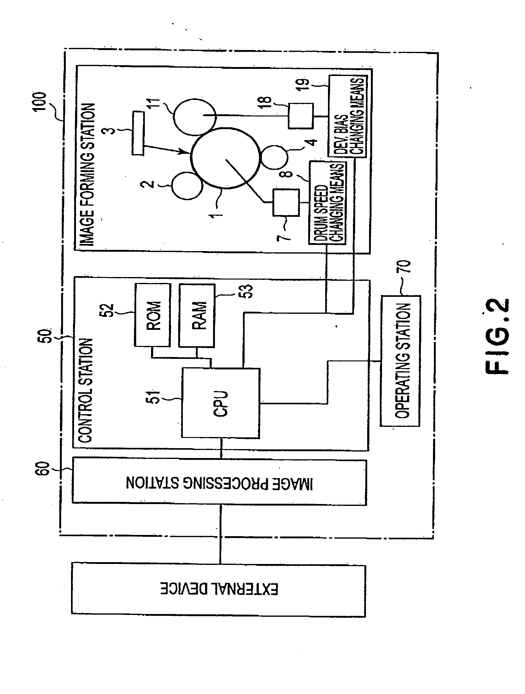
[0051] First, referring to FIG. 1, the general structure and operation of the image forming apparatus in the first embodiment of the present invention will be described. The image forming apparatus 100 in this embodiment is a laser beam printer capable of forming a full-color image, based on four color components, on recording medium such as recording paper, OHP sheet, fabric, etc., with the use of one of the electrophotographic image formation methods, in response to the image formation signals from a host such as a personal computer connected to the main assembly 100A of the image forming apparatus 100, or an external apparatus such as an original reading apparatus connected to the main assembly 100A and capable of optically reading an original and converting the obtained information about the original into electrical signals.

[0052] The image forming apparatus 100 has the rotatable photosensitive drum 1 as an image bear...

embodiment 2

[0093] Next, another embodiment, or the second embodiment, of the present invention will be described. The basic structure and operation of the image forming apparatus in this embodiment are virtually the same as those in the first embodiment. Thus, the components of the image forming apparatus in this embodiment, which are virtually identical or equivalent in structure and function to those in the first embodiment, are given the same referential symbols as those given for the description of the first embodiment, and will not be described in detail.

[0094] Referring to FIG. 6, also in this embodiment, a combination of AC and DC voltages is used as development bias. In this embodiment, however, AC and DC voltages are combined in such a manner that the development bias is provided with portions in which voltage oscillates and forms an oscillatory electric field, that is, an electrical field in which potential level alternates, and portions in which voltage does not oscillate, and ther...

embodiment 3

[0124] Next, another embodiment, or the third embodiment, of the present invention will be described. The basic structure and operation of the image forming apparatus in this embodiment are virtually the same as those in the first embodiment. Thus, the components of the image forming apparatus in this embodiment, which are virtually identical or equivalent in structure and function to those in the first embodiment, are given the same referential symbols as those given for the description of the first embodiment, and will not be described in detail.

[0125] In this embodiment, the image forming apparatus is controlled in density by controlling the speed of the development roller 11. More specifically, the image forming apparatus 100 in this embodiment is enabled to operate in the low speed printing mode, standard mode, and high speed printing mode. In the low speed printing mode, the ratio of the peripheral velocity of the development roller 11 relative to that of the photosensitive d...


PUM


Abstract

An image forming apparatus includes an image bearing member; a developer carrying member, disposed opposed to the image bearing member, for carrying a developer, wherein an electric field is formed between the developer carrying member and the image bearing member during a developing operation using the developer carrying member, and the electric field including an oscillating portion in which the electric field is an oscillating electric field, wherein a supply electric field of the oscillating electric field which is effective to supply the developer to the image bearing member from the developer carrying member is variably controllable in accordance with a peripheral speed of the image bearing member.

Description

FIELD OF THE INVENTION AND RELATED ART [0001] The present invention relates to an image forming apparatus which develops an electrostatic image formed on an image bearing member, into a visible image with the use of an electrophotographic method or the like. In particular, it relates to an image forming apparatus which develops an electrostatic latent image by forming an oscillatory electric field between the image bearing member and a developer bearing member. [0002] An electrophotographic image forming apparatus forms an electrostatic image on the surface of an image bearing member by uniformly charging the image bearing member with the use of a charging means, and then, exposing the surface of the uniformly charged image bearing member to a beam of light modulated with image formation data signals. This electrophotographic image is developed into a visible image by a developing means which uses developer. Then, this visible image formed of the developer is directly transferred on...

Claims


Application Information

Patent Timeline
IPC IPC(8): G03G21/14G03G15/06G03G15/08
CPCG03G2215/0634G03G15/0806
Inventor KAWAMURA, TAKESHISUZUKI, JUNNOGUCHI, BUNROSHIBATA, MASAHIRO
Owner CANON KK
Why Eureka
Try Eureka