Image forming apparatus

Active Publication Date: 2005-09-01
KONICA MINOLTA INC
View PDF4 Cites 114 Cited by
  • Summary
  • Abstract
  • Description
  • Claims
  • Application Information

AI Technical Summary

Benefits of technology

[0008] The present invention has been made in order to solve the foregoing problem. It is an object of the present invention to provide an image forming apparatus capable of securing rotation transmission accuracy between input/output axes without giving stress to a holding portion

Problems solved by technology

As a result, stress is given to members for holding input/output axis and a cover box of an image forming apparatus, which causes a fear of distortion.
Structure to

Method used


Image

  • Image forming apparatus
  • Image forming apparatus
  • Image forming apparatus

Examples


first embodiment

[0045] There will be described a first embodiment in detail by referring to drawings. In this embodiment, the present invention is applied to a tandem type color printer.

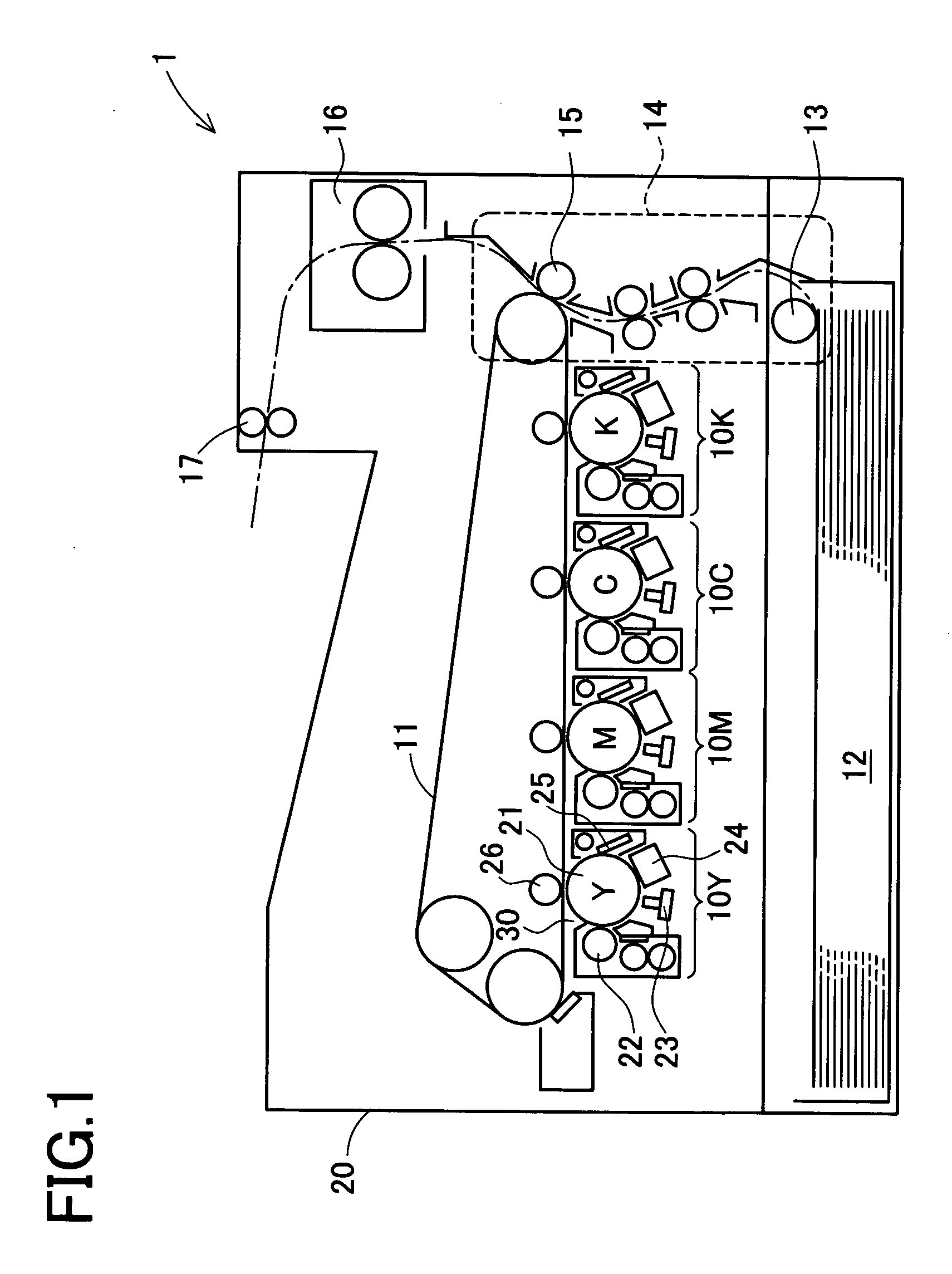
[0046] In a color printer 1 directed to this embodiment, as shown in FIG. 1, image forming sections of respective colors 10Y, 10M, 10C, and 10K are arranged along an intermediate image transfer belt 11. At the bottom portion of the color printer, there is attached a paper cassette 12. Sheets of paper in there are fed to a paper carrying section 14 by a paper feeding roller 13. An image formed on the intermediate image transfer belt 11 by superimposing respective color images through the image forming sections 10Y, 10M, 10C, and 10K is transferred onto a sheet of paper at a secondary image transfer section 15, and fixed at an image fixing section 16. A sheet of paper on which an image is thus formed is ejected by a paper ejecting roller 17. All of the above-mentioned structure is housed in a cover box 20.

[0047] Eac...

second embodiment

[0072] Hereinafter, the second embodiment of the present invention will be described in detail with reference to the accompanying drawings. This embodiment also concerns an application of the present invention to the tandem type color printer. The entire configuration of this embodiment is the same as FIG. 1 of the first embodiment.

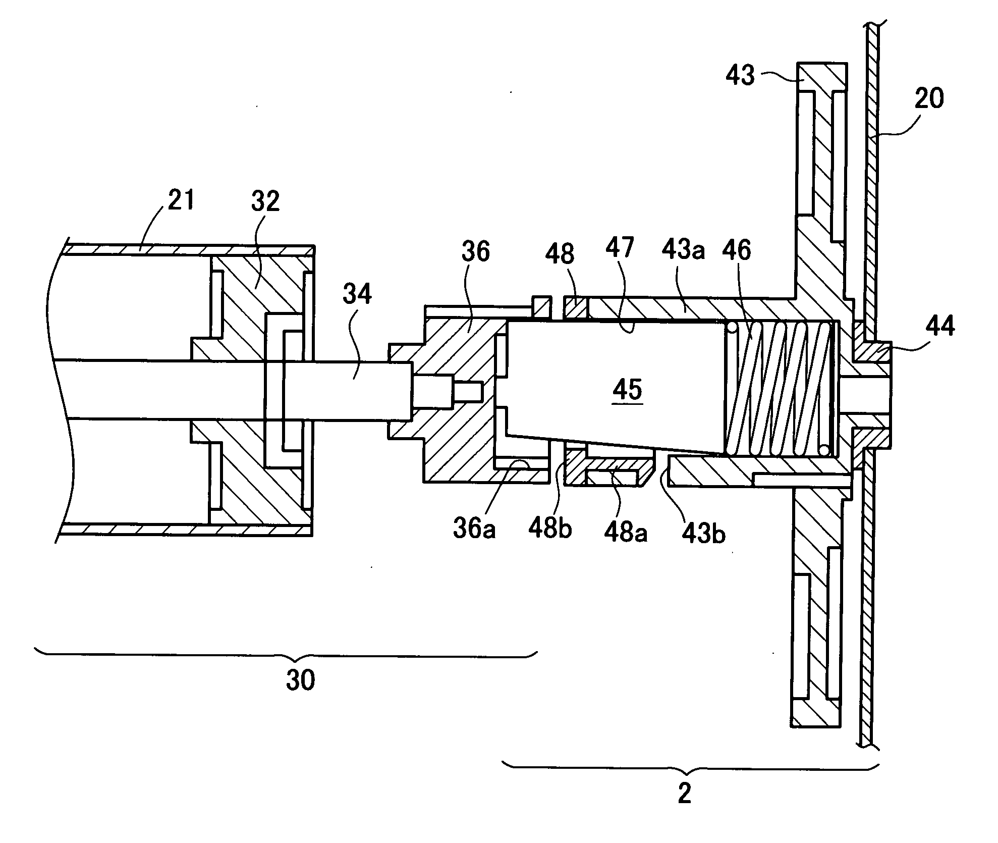
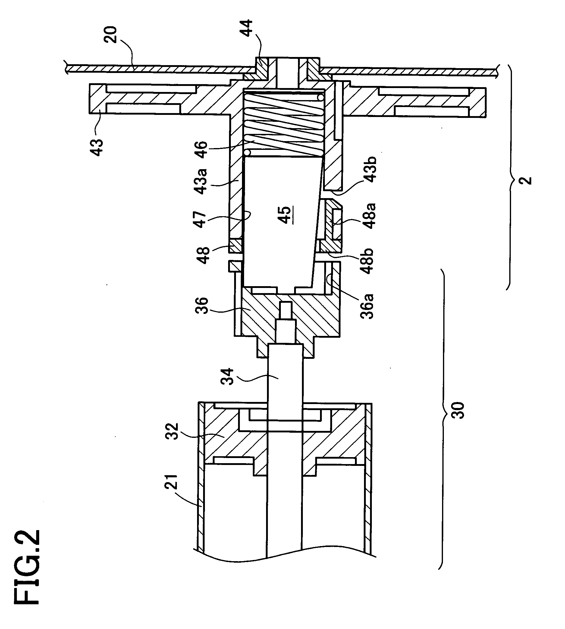
[0073] Next, FIGS. 11, 12 show an outline of the connecting portion of the main body 2 and image forming unit 30 of this embodiment. This connecting portion is disposed on a deeper side in FIG. 1 of the color printer. FIG. 11 shows a sectional view of this connecting portion. FIG. 12 is an exploded oblique perspective view of the right half of FIG. 11. In the image forming unit 30, as shown on the left side of FIG. 11, a flange 32 is fixed to an end portion of a photosensitive body 21 and the rotation shaft 34 of the photosensitive body 21 is fixed onto the flange 32.

[0074] On the side of the main body 2, as shown on the right side of FIG. 11, a gear 43...

third embodiment

[0091] Hereinafter the third embodiment of the present invention will be described in detail with reference to the accompanying drawings. This embodiment is different from the first embodiment in only the connecting portion between the image forming unit 30 and the main body 2. Because the entire structure thereof is substantially equal, only different points will be described here.

[0092]FIG. 17 shows the schematic structure of the connecting portion of this embodiment. In this Figure, the image forming unit 30 is represented on the right side thereof. The image forming unit 30 is held by the housing 31 and it includes a photosensitive body 21, a flange 32 and a shaft holder 33. The flange 32 is fixed to an end portion of the photosensitive body 21 and rotated integrally with the photosensitive body 21. The shaft holder 33 supports an end portion of the flange 32 rotatably and is fixed to the housing 31. A cylindrical fixing section 33a is formed at a left end portion in the Figure...


PUM


Abstract

It is intended to provide an image forming apparatus capable of securing rotation transmission accuracy among input/output axes without giving stress to a holding portion despite shaft misalignment and without using material of high strength. A color printer 1 comprises a main body 2 and an image forming unit 30 removable from the main body 2. The main body 2 includes a gear 43 for receiving rotary driving force to the image forming unit 30 and a joint 45 and the image forming unit 30 has a coupling 36 for receiving rotary driving force from the main body 2. Furthermore, a joint holder section 43a for the gear 43 and the coupling 36 has a contact hole 47, and contact hole 36a, respectively and both ends of the joint 45 are inserted in those holes. The contact holes 47 and 36a are in not-twisted triangle pole shape and the joint 45 is in twisted triangle pole shape.

Description

[0001] This application is based on Applications No. 2004-051346 and No. 2004-137187 filed in Japan, contents of which are hereby incorporated by reference. BACKGROUND OF THE INVENTION [0002] 1. Field of the Invention [0003] The present invention relates to an image forming apparatus such as a printer, a copier, and the like. More particularly, it relates to an image forming apparatus of which process unit including a photosensitive body or an intermediate transfer image belt, or the like is removable. [0004] 2. Description of Related Art [0005] There have conventionally been devised image forming apparatuses of which wear-out portion such as photosensitive drum or the like is made in a removable unit so that an end user can replace it with a new one. For example, a tandem type image forming apparatus provided with four image forming sections for respective colors, namely, yellow, magenta, cyan, and black, has four image forming units for the respective colors. In case such an image...

Claims


Application Information

Patent Timeline
IPC IPC(8): G03G15/00G03G21/16
CPCG03G15/757G03G2221/1657G03G2215/0119
Inventor TOSO, YOSHIYUKIKONDO, NOZOMUYAMADA, KOUWATANABE, TOORUKATOGI, SYUICHITASHIRO, SHIGERUKAGAWA, TETSUYA
Owner KONICA MINOLTA INC
Why Eureka
Try Eureka