Soil test box

a test box and soil technology, applied in the field of soil test boxes, can solve the problems of difficult and expensive periodic inspection and replacement, time-consuming and expensive, and significant impact on development costs of out-of-work of this kind

Inactive Publication Date: 2005-09-01
JAMES HARDIE INT FINANCE BV
View PDF23 Cites 18 Cited by
  • Summary
  • Abstract
  • Description
  • Claims
  • Application Information

AI Technical Summary

Benefits of technology

[0030] measuring the effect of t

Problems solved by technology

Product performance and properties are two of the most important features of building products, particularly products that are to be installed underground which makes periodic inspection and replacement difficult and expensive.
However, testing under actual conditions can be very difficult, time consuming and expensive, particularly when the product is to be installed underground.
Because it is both costly and time consuming to build and maintain these soil test box

Method used


Image

  • Soil test box
  • Soil test box
  • Soil test box

Examples


Embodiment Construction

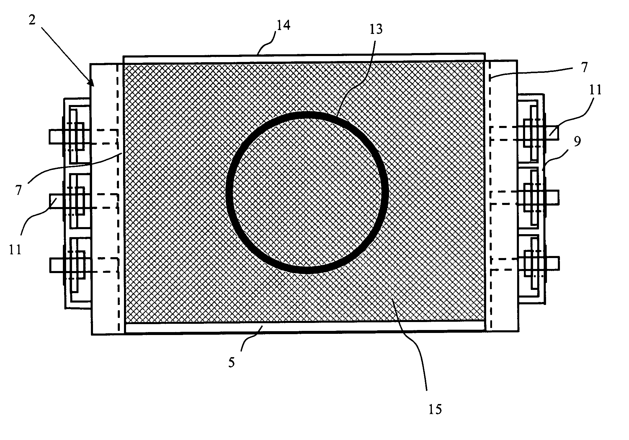
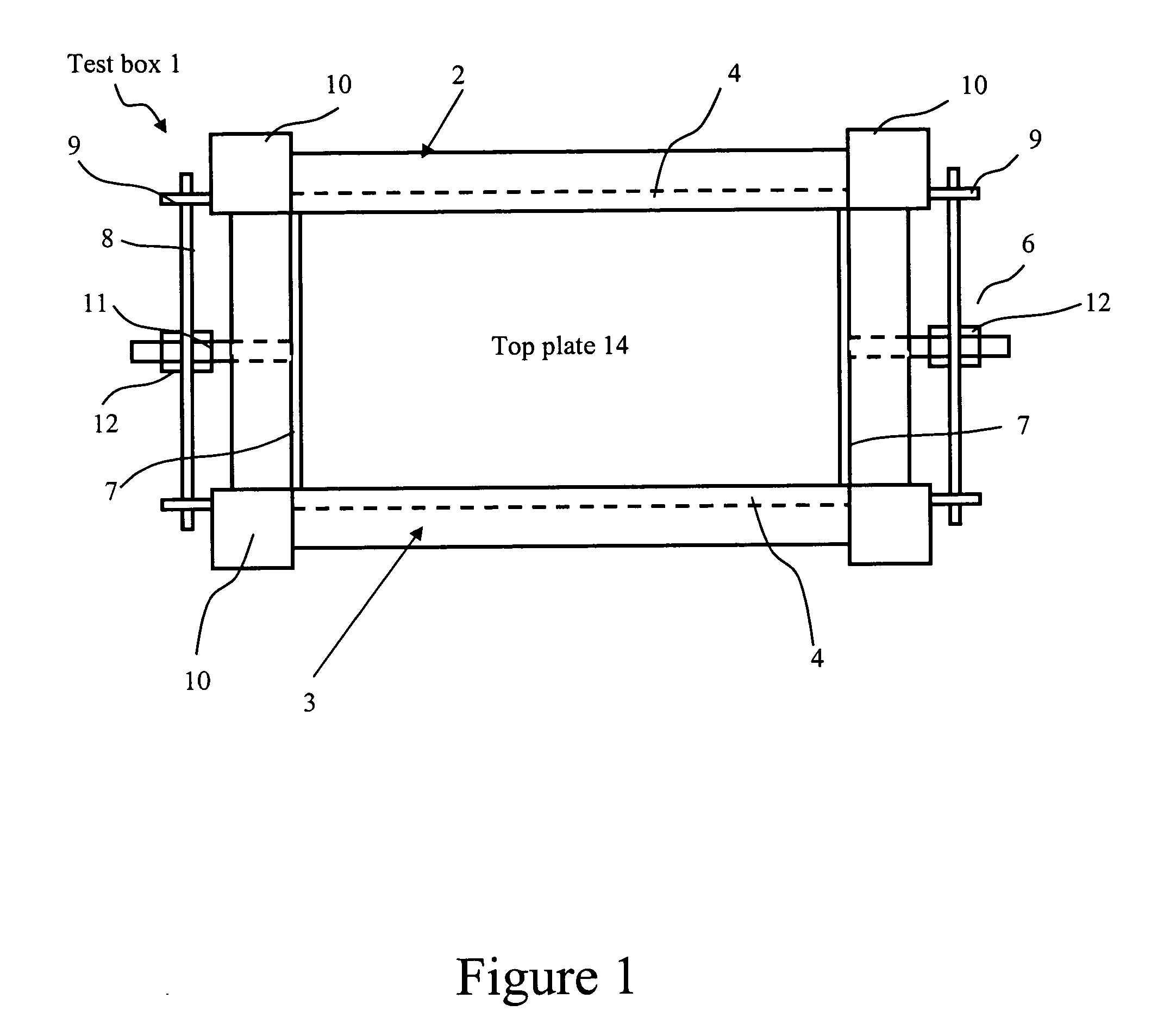
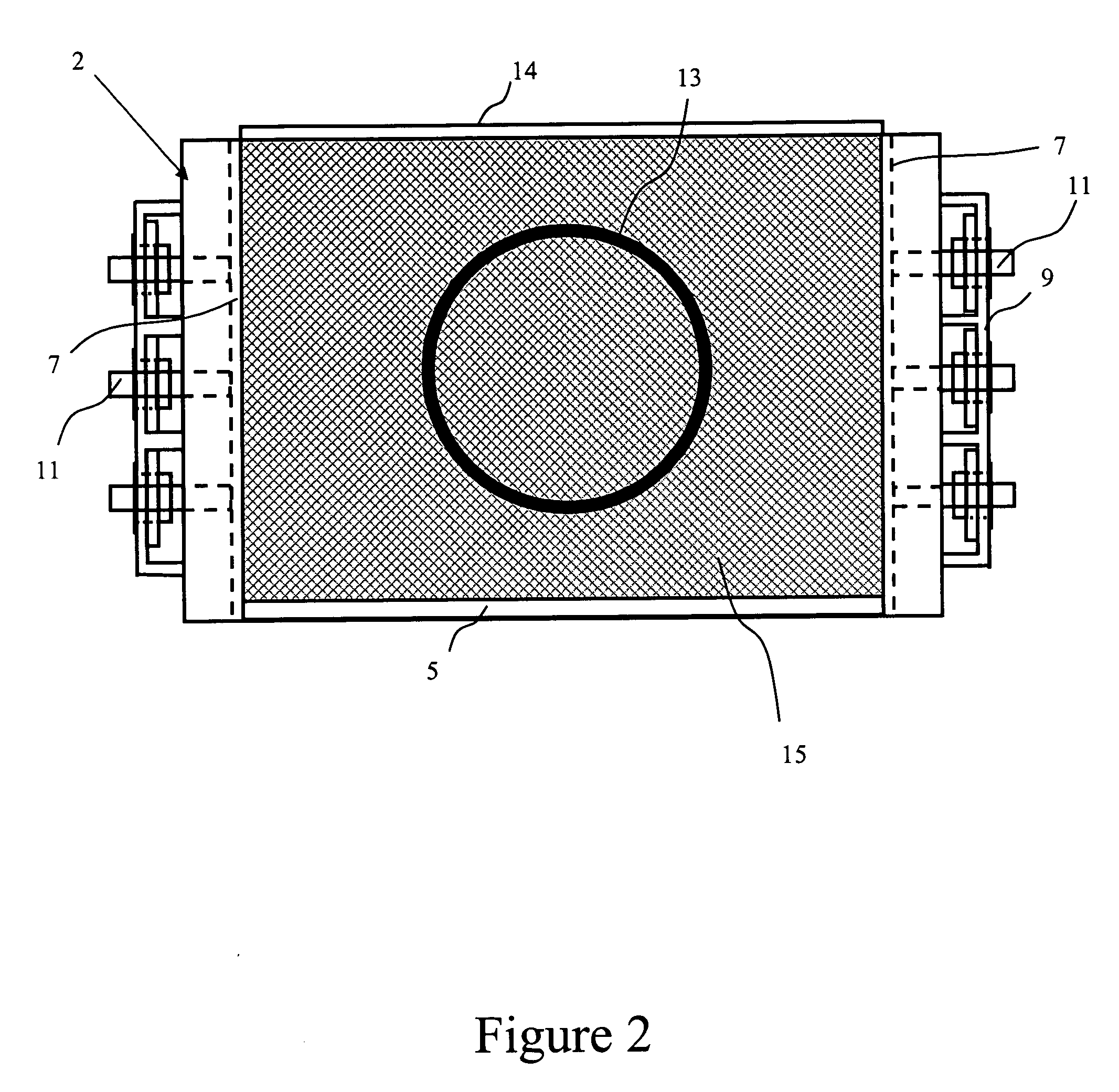
[0039] Referring to FIGS. 1-3, one embodiment of the invention provides a soil test box 1 specifically configured for use in testing pipes. The box includes a rigid external frame 2 that defines the exterior of the container 3. Fixed end portions in the form of end plates 4 and a fixed base portion 5 are secured to the frame. Resiliently movable end portions shown generally at 6 form the remaining two walls of the container 3. These end portions include end plates 7, which are ideally made of a material such as steel or aluminum, are mounted with the frame 2 via an intermediate spring mechanism. This spring mechanism includes a set of spaced apart generally parallel leaf springs 8, each mounted at its ends with flanges 9 extending outwardly from the respective corner posts 10 of the frame. The end plates 7 are then connected with the leaf springs 8 by means of respective connecting rods 11 extending from the rigid end plates 7. The connecting rods are bolted securely to the leaf spr...


PUM


Abstract

A soil test apparatus (1) for testing products in subterranean soil installations. The apparatus includes a container (3) for receiving soil (15) and a product (13) to be buried therein for testing. The container includes a base (5), sides (4, 7) and a top opening adapted directly or indirectly to receive a load. At least one of the sides is configured to permit some movement or deformation under application of the load to the soil in the container so as to simulate larger scale installation conditions. A method of testing products in subterranean soil installations using the soil test apparatus comprises setting up the apparatus to permit some movement or deformation of at least one of the sides (4, 7) under predetermined load conditions. The container is partially filled with soil (15). The product (13) is positioned within the container. The product is buried by the addition of further soil (15). The load is applied to the soil via the top opening of the container. An effect of the load on the product, the container, or the soil is measured.

Description

CROSS-REFERENCE TO RELATED APPLICATION [0001] This application claims the benefit of U.S. Provisional Application No. 60 / 406,408, filed Aug. 26, 2002, the entirety of which is hereby incorporated by reference.BACKGROUND OF THE INVENTION [0002] 1. Field of the Invention [0003] The present invention relates in certain embodiments to an apparatus and associated method for workshop or laboratory testing of products in simulated subterranean soil installations. [0004] Preferred embodiments have been developed for specific use in the testing of pipes and more particularly concrete pipes, and will be described hereinafter with reference to this field of use. However, it will be appreciated that the invention is readily adapted for use in simulated subterranean soil testing of other products. [0005] 2. Description of the Related Art [0006] Product performance and properties are two of the most important features of building products, particularly products that are to be installed undergroun...

Claims


Application Information

Patent Timeline
IPC IPC(8): G01N3/02G01N3/10G01N3/12G01N33/24
CPCG01N3/10G01N3/12G01N33/24Y10T436/25G01N2203/0232G01N2203/0246G01N2203/0274G01N2203/023
Inventor PETHER, JOHNSHARMAN, DAVID
Owner JAMES HARDIE INT FINANCE BV
Why Eureka
Try Eureka