Insulation cap and joined electrical wire using the same
- Summary
- Abstract
- Description
- Claims
- Application Information
AI Technical Summary
Benefits of technology
Problems solved by technology
Method used
Image
Examples
first embodiment
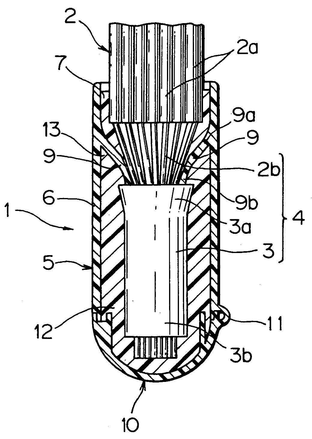
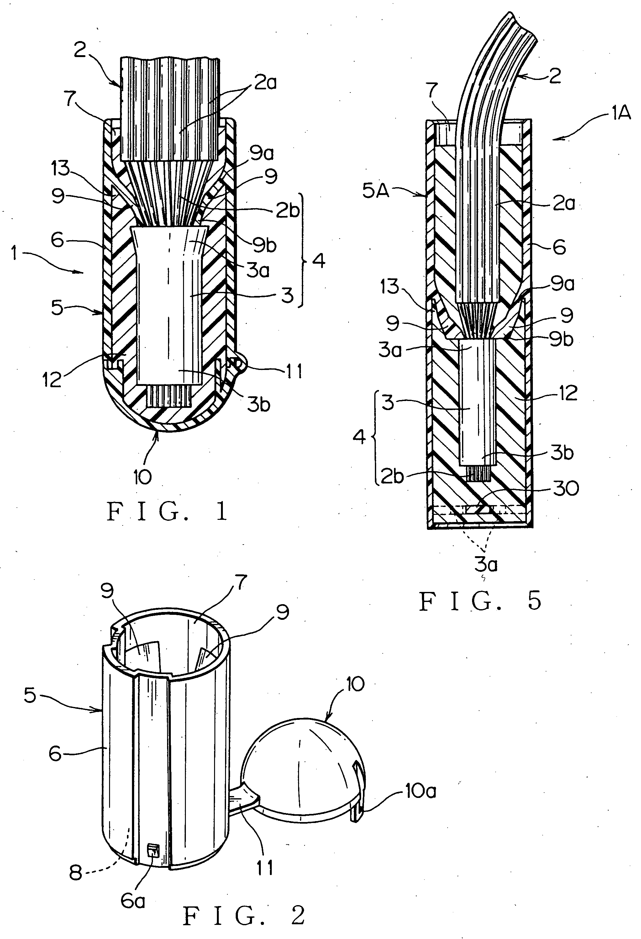
[0049] Embodiments of an insulation cap according to the present invention will be described with reference to drawings. FIG. 1 shows the insulation cap and a joined electrical wire using the insulation cap according to this invention.
[0050] The joined electrical wire 1 includes a plurality of covered wires 2, an electro-conductive sleeve 3 for joining cores 2b at terminal side of the covered wires 2, a wire joint 4, a insulation cap 5 being mounted at the wire joint 4 and insulation covers 2a near the wire joint 4, and a sealant 12 for filling inside of the insulation cap 5.
[0051] The insulation cover 2a at the terminal side of the covered wire 2 is striped to expose a predetermined length of the core 2b. The exposed cores 2b are arranged in the same direction and twisted for preventing wire elements from being loosed, and crimp-contacted with the electro-conductive sleeve 3 for joining covered wires to be connected electrically with each other. The wire joint 4 is formed with the...
third embodiment
[0085] an insulation cap and a joined electrical wire using the insulation cap are described with reference to FIGS. 9-14. An insulation cap 5B differs from previous embodiments in a point that the insulation cap 5B includes a small diameter receiving section 42 projecting from a bottom portion 41 of the large diameter cap main body 6. Other structuring components are common to the previous embodiments, so that the same markings are applied and detailed description is omitted herein.
[0086] The large diameter cap main body 6 has a cylindrical body to cover the insulation cover 2a near the wire joint 4. The cap main body 6 has a top opening at upper side and a bottom portion 41 at bottom side. The bottom portion 41 is formed with three fastening holes 41a for fastening a lower molding die for molding the flexible fastener 9 (FIGS. 9, 12).
[0087] The three flexible fasteners 9 are located with even intervals along a circumference of a inner wall of the cap main body 6. Thereby, the wir...
PUM
 Abstract
Description
Claims
Application Information
 - R&D
- Intellectual Property
- Life Sciences
- Materials
- Tech Scout
- Unparalleled Data Quality
- Higher Quality Content
- 60% Fewer Hallucinations
Browse by: Latest US Patents, China's latest patents, Technical Efficacy Thesaurus, Application Domain, Technology Topic, Popular Technical Reports.
© 2025 PatSnap. All rights reserved.Legal|Privacy policy|Modern Slavery Act Transparency Statement|Sitemap|About US| Contact US: help@patsnap.com


