

Method of controlling laser power and optical disk player
- Summary
- Abstract
- Description
- Claims
- Application Information
AI Technical Summary
Benefits of technology
Problems solved by technology
Method used
Image

Examples
first embodiment
[0050]A first embodiment will be explained with reference to FIGS. 1–3.
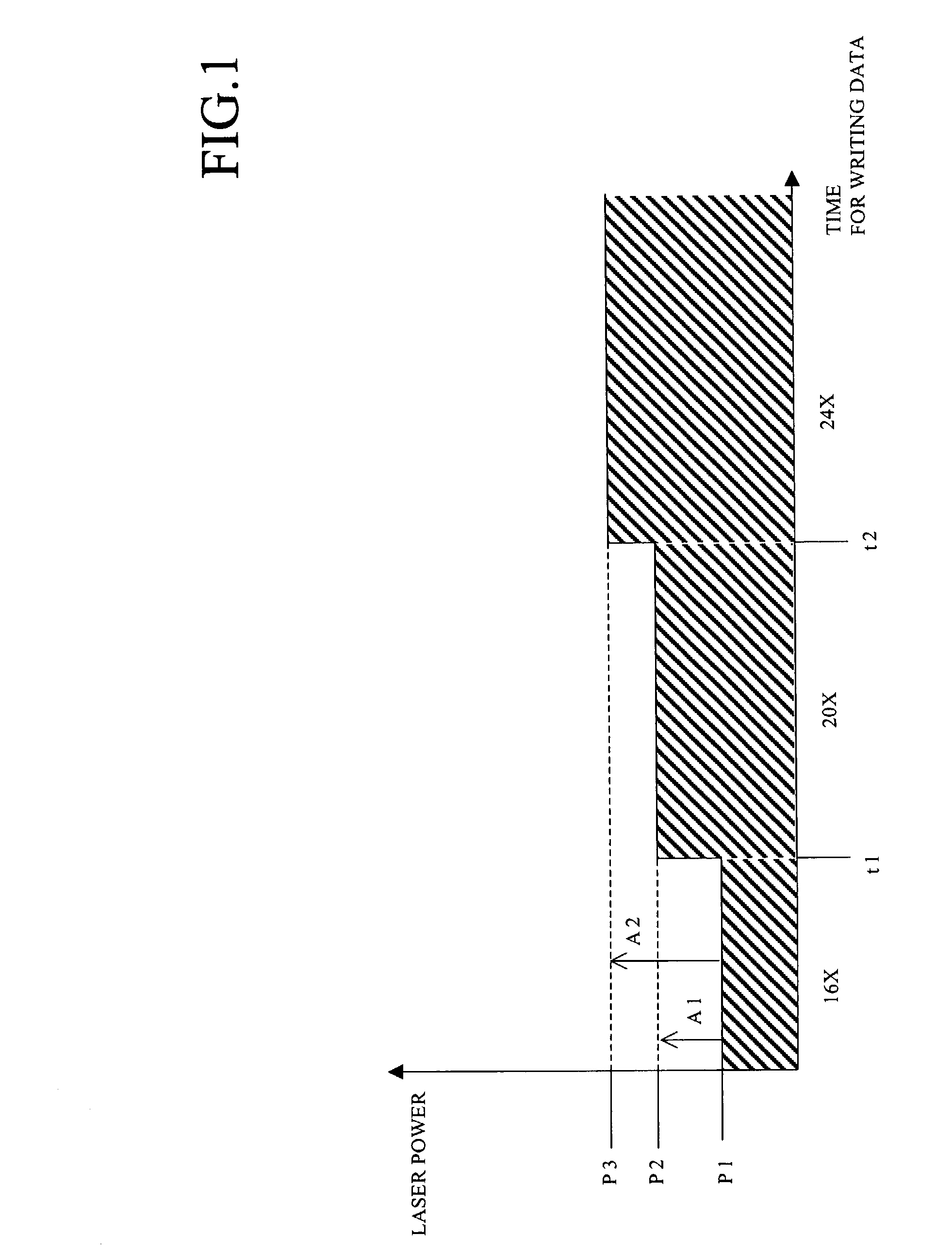
[0051]Firstly, action of an optical disk player of the first embodiment will be explained with reference to FIG. 1.
[0052]In FIG. 1, a horizontal axis of is time for writing data; a vertical axis is laser power for writing data.
[0053]In the zone CLV manner, as described in BACKGROUND OF THE INVENTION, the linear velocity for writing data on an optical disk is accelerated by stages.
[0054]In the present embodiment, firstly data are written with 16× linear velocity. The laser power is P1. The value P1 is determined by the OPC test, which has been executed before writing data.
[0055]After the laps of prescribed time t1 from a start, the linear velocity is changed to 20× linear velocity. At that time, the laser power is changed to P2 corresponding to 20× linear velocity. The laser power p1 plus a correction value A1 is the laser power P2.
[0056]After the laps of prescribed time t2 from the start, the linear velocity is c...
second embodiment
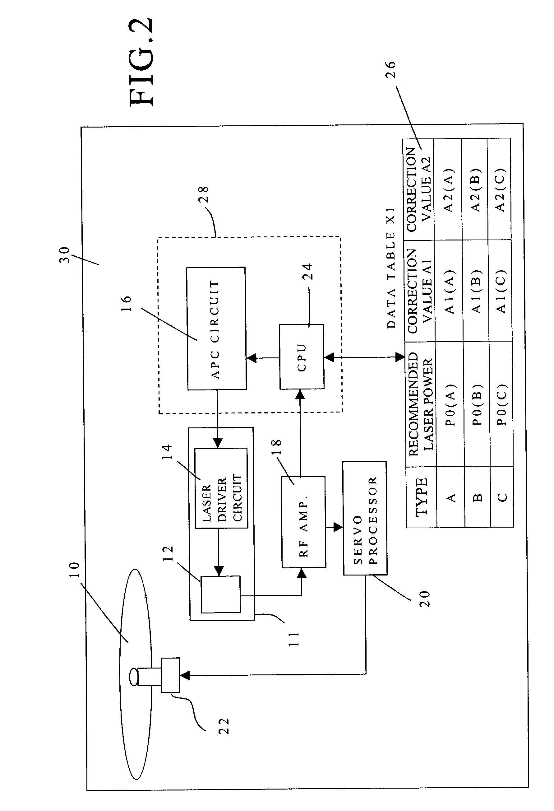
[0084]A second embodiment will be explained with reference to FIGS. 4–6. Note that, structural elements explained in the first embodiment are assigned the same symbols, and explanation will be omitted.
[0085]Firstly, action of the optical disk player of the second embodiment will be explained.
[0086]In the second embodiment, the laser power correction values are determined according to temperature around the laser diode 12.
[0087]Temperature of the laser diode 12 is made higher, the laser power of the laser diode 12 is made smaller. On the other hand, the temperature of the laser diode 12 is made lower, the laser power of the laser diode 12 is made greater.
[0088]In the second embodiment, fixed correction values are not merely added to the laser power when the linear velocity is changed. To precisely control the laser power in the zone CLV manner, correction values corresponding to temperature around the laser diode 12 are added. In the present embodiment, the correction values correspo...
third embodiment
[0118]A third embodiment will be explained with reference to FIGS. 7–9. Note that, structural elements explained in the foregoing embodiments are assigned the same symbols, and explanation will be omitted.
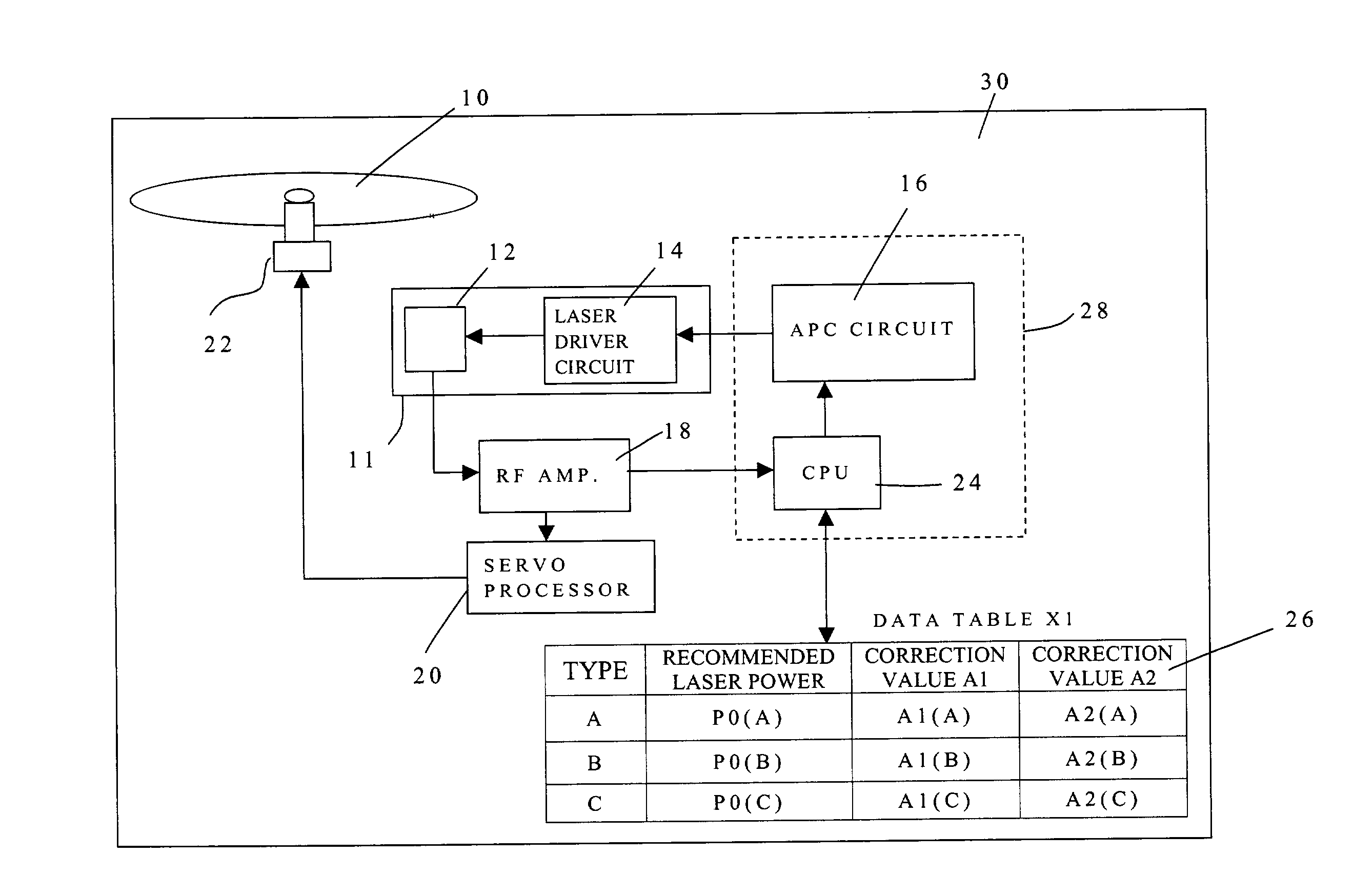
[0119]In the third embodiment, the correction values A1 and A2 (see FIG. 1) are calculated from standard correction values a1, a2, b1, b2, c1 and c2, which have been previously determined on the basis of types of the optical disk without considering temperature, and temperature coefficients α1, α2, β1, β2, γ1, γ2, δ1 and δ2, which have been previously determined so as to correct the standard correction values according to the measured temperature.
[0120]In a general laser diode, even if the laser diode irradiates with prescribed laser power, writing efficiency under the High Temperature is lower than that under the Ordinary Temperature due to variation of wavelength. On the other hand, writing efficiency under the Low Temperature is higher than that under the Ordinary Temperature du...
PUM
 Abstract
Description
Claims
Application Information