Flexible couplings

a coupling and flexible technology, applied in the direction of yielding couplings, couplings, mechanical devices, etc., can solve problems such as couplings to come apart, and achieve the effect of facilitating torque transmission

Inactive Publication Date: 2005-09-01
ATR SALES
View PDF13 Cites 19 Cited by
  • Summary
  • Abstract
  • Description
  • Claims
  • Application Information

AI Technical Summary

Benefits of technology

[0011] Accordingly, disclosed hereafter is a flexible coupling including a first hub having an inner face and a flexible insert having a plurality of exterior lobes and a plurality of interior lobes. A retainer ring is provided having an interior which engages the exterior lobes of the first hub, while a second hub has an exterior surface contoured to engage the interior lobes. The exterior and interior lobes may each have a rounded contour formed between two flat faces, which facilitates torque transmission.

Problems solved by technology

However, if the shafts are grossly misaligned, the metal band will “walk-off” the belt, causing the coupling to come apart.

Method used


Image

  • Flexible couplings
  • Flexible couplings
  • Flexible couplings

Examples


Embodiment Construction

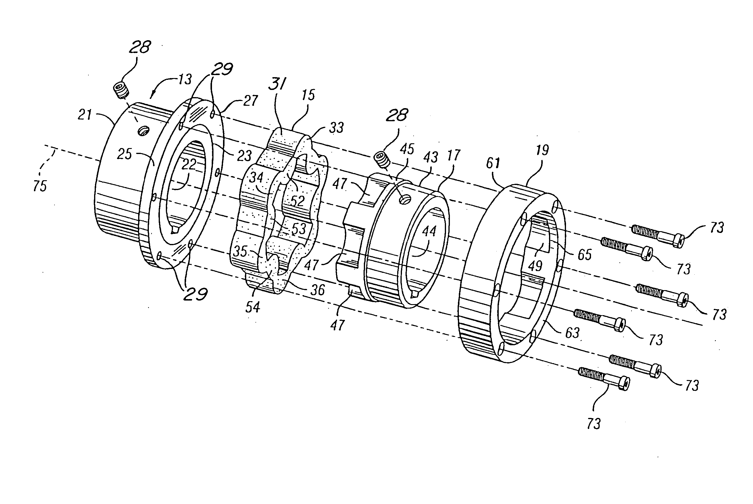
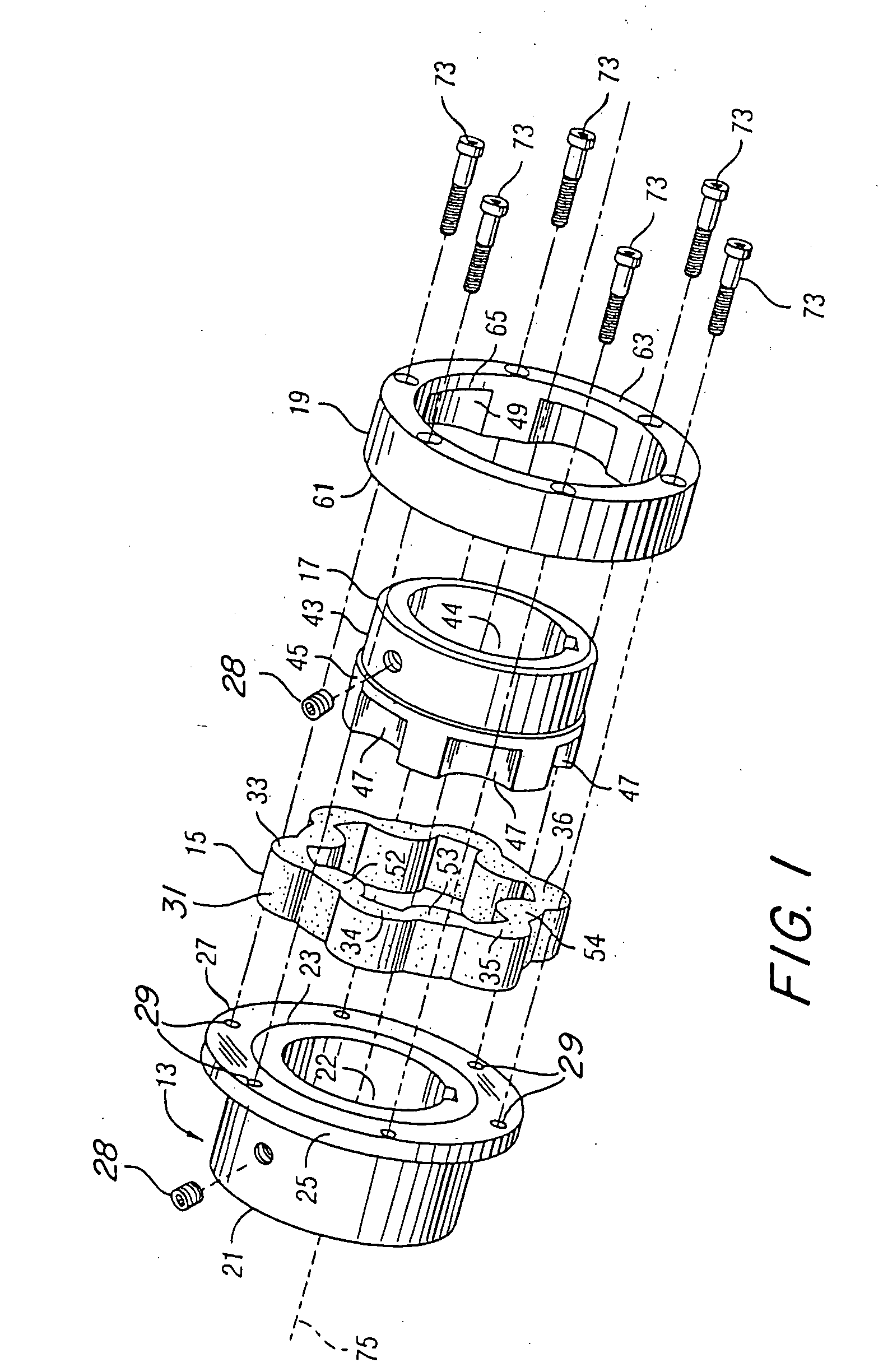
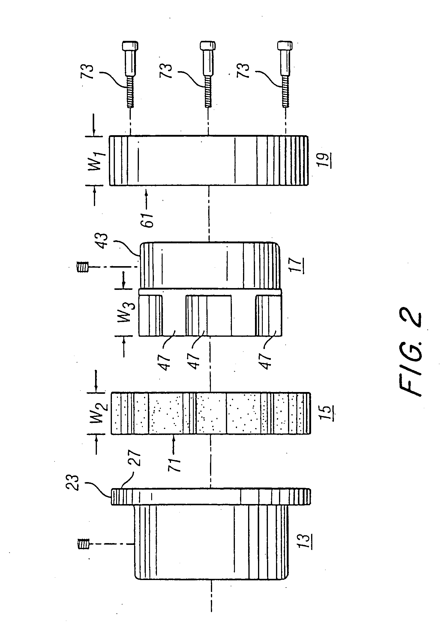
[0025] The coupling of the illustrative embodiment includes a first hub 13, a flexible insert 15, a second hub 17 and a retainer member 19. The first hub 13 includes an interior bore 22, a first cylindrical segment 21 and a mounting flange 23 having a circular outer edge 25. The face 27 of the flange 23 has a number of mounting holes 29 therein, each of which lies equally spaced on a circle of lesser diameter than that of the outer edge 25. Conventional fastening devices such as screw 28 may be used to secure the hubs to respective shafts.

[0026] The insert 15 is preferably fabricated from a flexible material such as, for example, a suitable urethane, and is preferably split so as to facilitate “wraparound” installation. The outer surface 31 of the insert 15 features a number of equally spaced exterior lobes 33, 34, 35, 36, 37, 38 projecting therefrom. The lobes, e.g., 33, are formed about equally spaced radii extending from the center of the insert 15. The interior surface of the i...


PUM


Abstract

A flexible coupling including a first hub having an inner face, a flexible insert having a plurality of exterior lobes and a plurality of interior lobes, a retainer ring having an interior which engages the exterior lobes of the flexible insert, and a second hub having an exterior surface contoured to engage the interior lobes of the flexible insert.

Description

CONTINUING APPLICATION DATA [0001] This application is a continuation-in-part of the application of Anthony L. Hauck filed Aug. 4, 2004, and entitled “Flexible Couplings” which is a continuation-in-part of U.S. application Ser. No. 10 / 107,285 filed Mar. 26, 2002.BACKGROUND OF THE INVENTION [0002] 1. Field of Invention [0003] The invention set forth in this specification pertains to new and improved flexible couplings and, more particularly, to such couplings having advantageous features of both shear and compression style couplings. [0004] 2. Description of Related Art [0005] Flexible couplings have long been used for the purpose of transmitting rotation from one shaft to another. Such couplings are normally used in order to accommodate comparatively minor shaft alignment problems such as are occasionally encountered because of manufacturing or assembly errors. Because of the fact that these devices are widely used and have been known and used for many years, many different types of...

Claims


Application Information

Patent Timeline
Patent Type & Authority Applications(United States)
IPC IPC(8): F16D3/68F16D3/76
CPCF16D3/76F16D3/68
Inventor HAUCK, ANTHONY L.
Owner ATR SALES
Why Eureka
Try Eureka