Mechanism for providing controllable angular orientation while transmitting torsional load

a technology of torsional load and angular orientation, which is applied in the direction of directional drilling, surveying, and borehole/well accessories, etc., can solve the problems of complex construction and operation of devices, and the inability of devices to control and adjust orientation, etc., and achieve the effect of relieving stress

Inactive Publication Date: 2011-03-31
DRECO ENERGY SERVICES ULC
View PDF13 Cites 11 Cited by
  • Summary
  • Abstract
  • Description
  • Claims
  • Application Information

AI Technical Summary

Benefits of technology

[0020]However, as the central sleeve is moved from its upper position toward its lower position, the central sleeve's lower ratchet teeth will begin engaging the ratchet teeth of the lower ratchet member before the central sleeve's upper ratchet teeth are fully disengaged from the upper ratchet member. As well, due to the previously-noted offset between the central sleeve's ratchet teeth and the ratchet teeth of the lower ratchet member, the continued downward movement of the central section's ratchet teeth into the ratchet teeth of the lower ratchet member will force the lower ratchet member to rotate approximately one-half of a ratchet tooth interval relative to the mandrel, due to the tips of the central sleeve's lower ratchet teeth bearing downward against the sloped faces of the ratchet teeth of the lower ratchet member. This limited rotational displacement of the lower ratchet member is possible because, as previously noted, the splines in the lower splined section of the mandrel are narrower than the corresponding grooves in the lower ratchet member. During this limited rotational displacement, any springs or other biasing means associated with the lower ratchet member will be compressed or otherwise stressed as the mandrel splines move in an arcuate path within the lower ratchet member grooves.
[0021]As the central sleeve reaches its lower position, and as the central sleeve's upper ratchet teeth become fully disengaged from the upper ratchet member, torsional loads acting on the mandrel (e.g. from a mud motor) will cause a sudden angular displacement of the mandrel relative to the central sleeve, while concurrently relieving stresses induced in the biasing means (if present) during the movement of the central sleeve. The amount of this angular displacement will correspond to one-half of the ratchet tooth spacing. Because the central sleeve cannot rotate relative to the tool housing by virtue of the spline / groove connection therebetween, the effect of the angular displacement between the mandrel and the central sleeve is to create the same angular displacement between the tool housing and the mandrel—and therefore between the tool housing and any mud motor or other tool or appurtenance coupled to the mandrel.

Problems solved by technology

However, when drilling with coiled tubing, which cannot easily be rotated from surface, orientation control must be accomplished using means capable of controlling the angular orientation of the mud motor relative to the coiled tubing.
Such devices are generally very complicated in construction and operation, with large numbers of components.
The devices also do not allow orientation to be controlled and adjusted while being subjected to torsional loads (such as under normal drilling conditions).

Method used


Image

  • Mechanism for providing controllable angular orientation while transmitting torsional load
  • Mechanism for providing controllable angular orientation while transmitting torsional load
  • Mechanism for providing controllable angular orientation while transmitting torsional load

Examples


Embodiment Construction

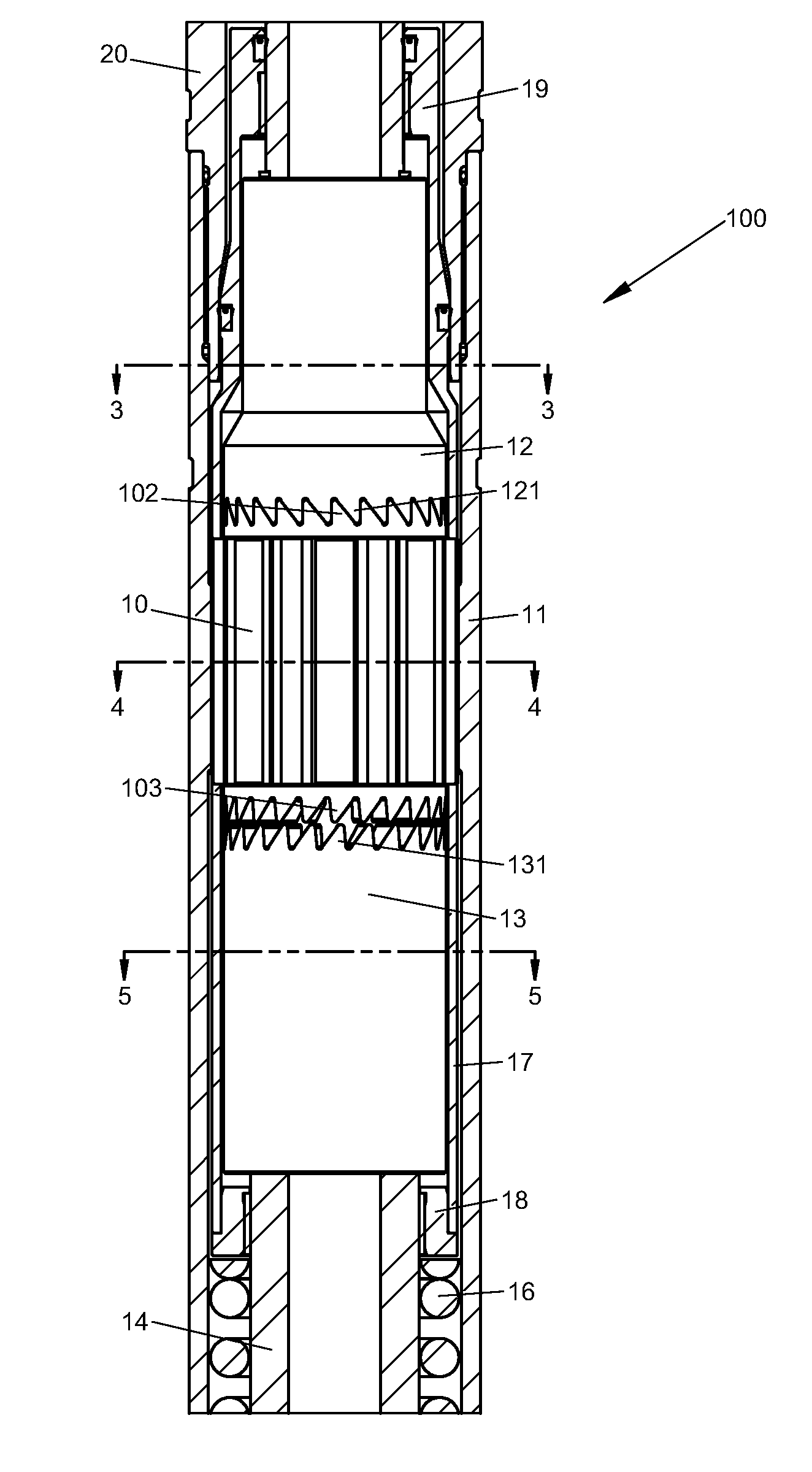
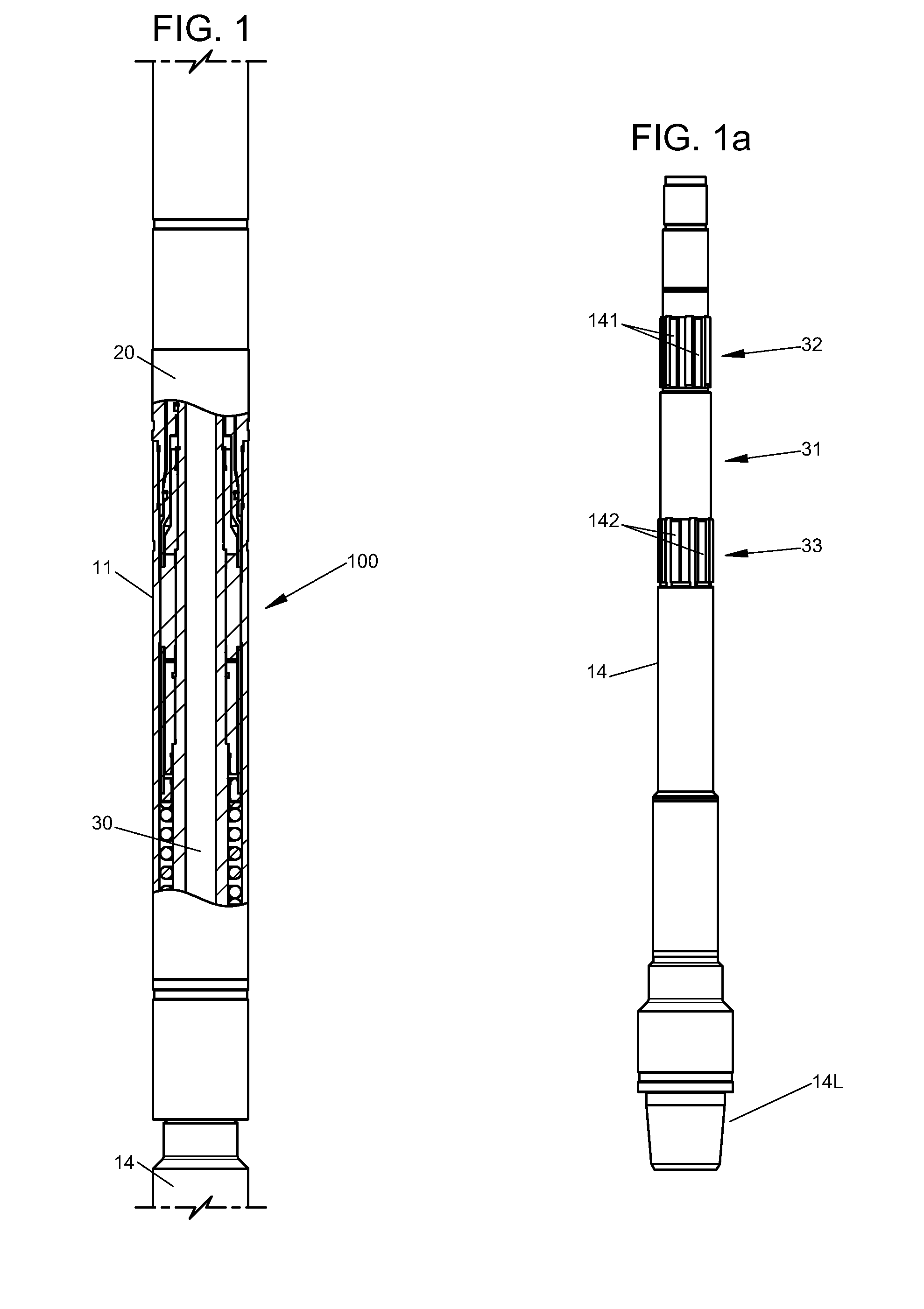
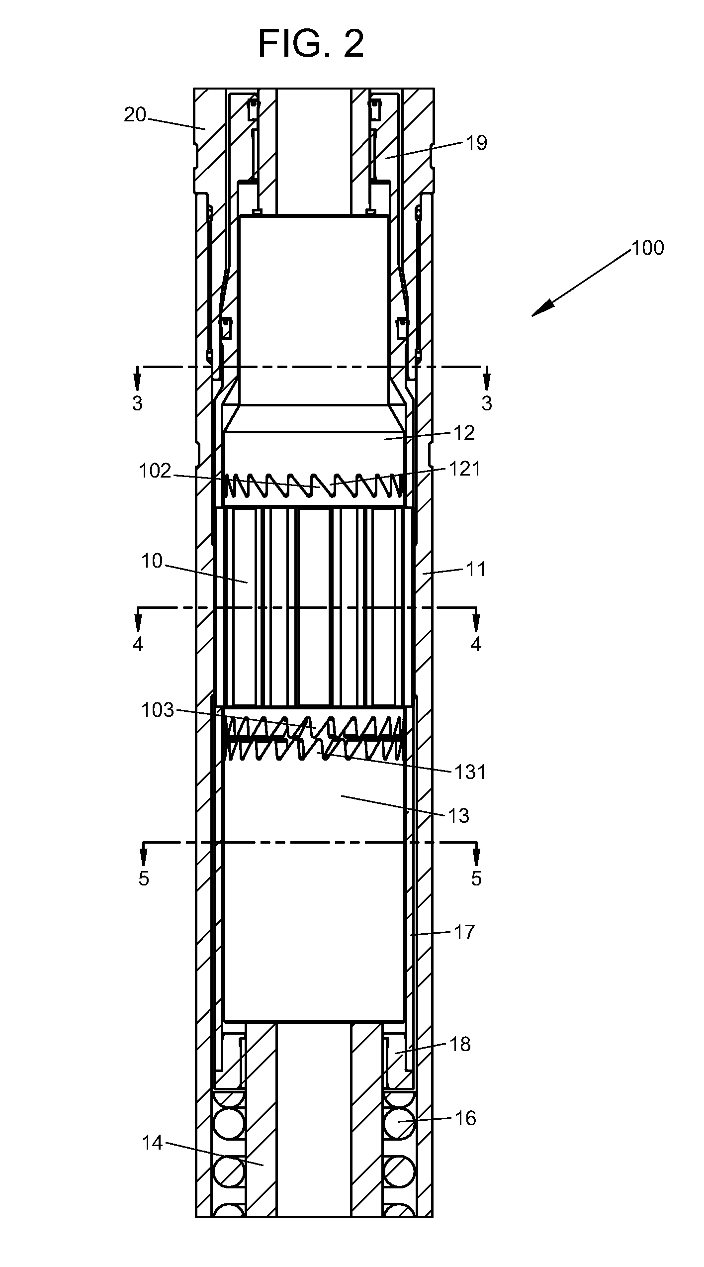
[0042]FIG. 1 illustrates an angular orientation mechanism 100 in accordance with one embodiment of the present invention, incorporated within a string of tubular elements constituting a downhole tool. FIG. 1 depicts one possible orientation of the downhole tool relative to a wellbore, with the tool comprising a cylindrical tool housing 20 (typically made up from a plurality of tool housing members) having an upper end 20U which may be coupled to the lower end of a pipe string or coiled tubing string (not shown), or to other tools or components that are coupled to the lower end of the string. For convenience, the adjectives “upper” and “lower” are used in this patent specification in reference to various components as if mechanism 100 were at all times vertically oriented as in FIG. 1. It will be appreciated, however, that these terms are used in a relative sense only, as the mechanism may be used in a variety of different orientations (such as during directional drilling operations)...


PUM


Abstract

A mechanism for adjusting the relative angular orientation of two coaxial components includes a mandrel having a cylindrical central section between upper and lower splined sections, a sleeve rotatably and slidably disposed around the mandrel's central section, and generally cylindrical upper and lower ratchet members positioned, respectively, about the mandrel's upper and lower splined sections. The ratchet members have internal grooves which receive the mandrel splines for torsional load transfer while permitting limited rotation relative to the mandrel, but their axial positions relative to the mandrel are fixed. The upper and lower ends of the sleeve have circumferentially-arrayed ratchet teeth engageable, respectively, with corresponding teeth on the upper and lower ratchet members. The central sleeve has torque-transferring external splines slidable within matching grooves on the inner surface of a cylindrical tool housing enclosing the mechanism. The mandrel is rotatable relative to the housing, but its axial position is fixed. The teeth of the sleeve and ratchet members are configured such that movement of the sleeve from a position engaging the upper ratchet member to a position engaging the lower ratchet member, or vice versa, will effect an incremental angular shift of the mandrel relative to the tool housing, while maintaining effective transfer of torsional loads therebetween.

Description

[0001]This application is the U.S. National Stage under 35 U.S.C. §371 of International Patent Application No. PCT / US2009 / 045490 filed May 28, 2009, which claims the benefit of U.S. Provisional Patent Application Ser. No. 61 / 057,110 filed May 29, 2008, entitled “Mechanism For Providing Controllable Angular Orientation While Transmitting Torsional Load.”STATEMENT REGARDING FEDERALLY SPONSORED RESEARCH OR DEVELOPMENT[0002]Not applicable.FIELD OF THE INVENTION[0003]The present invention relates in general to mechanisms for providing controllable angular orientation between an outer tubular element and a coaxial inner tubular element while transmitting torsional load between the outer and inner tubular elements. More particularly, the invention is directed to such mechanisms which can be incorporated in a downhole tool coupled within a drill string in a wellbore to provide controllable angular orientation between the sections of the string above and below the tool, while the mechanism i...

Claims


Application Information

Patent Timeline
Patent Type & Authority Applications(United States)
IPC IPC(8): E21B7/04
CPCE21B7/067E21B7/06E21B47/09E21B47/024
Inventor PRILL, JONATHAN RYANMARCHAND, NICHOLAS RYAN
Owner DRECO ENERGY SERVICES ULC
Why Eureka
Try Eureka