

Method and apparatus for designing circuits using high-level synthesis
- Summary
- Abstract
- Description
- Claims
- Application Information
AI Technical Summary
Benefits of technology
Problems solved by technology
Method used
Image

Examples
Embodiment Construction
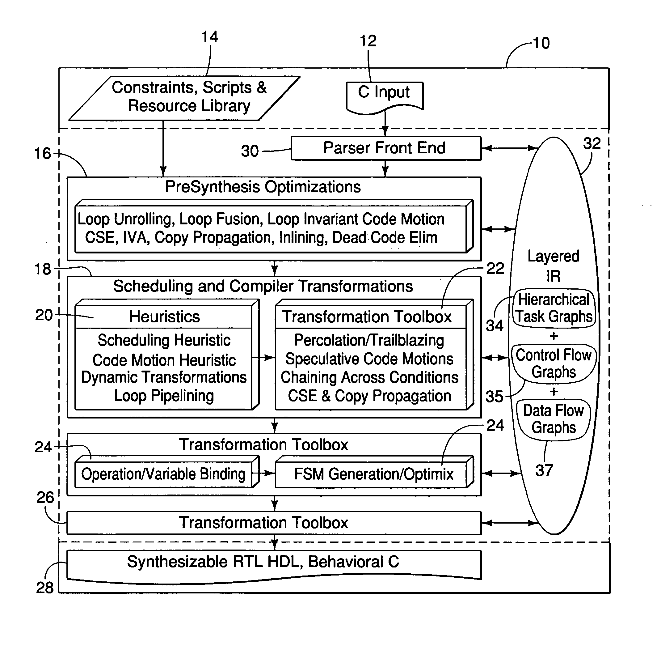
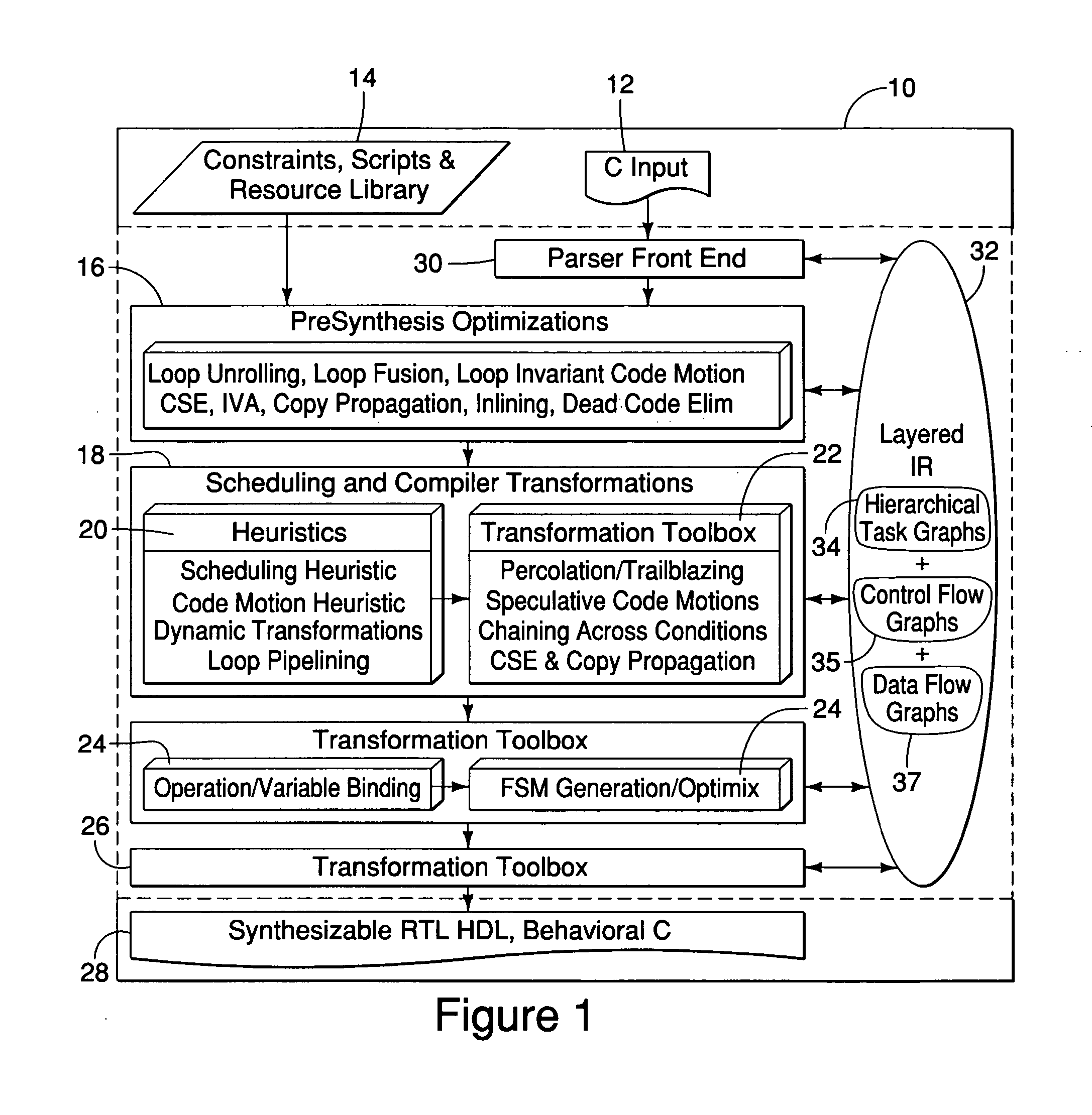
[0026] One embodiment of the invention relates to a parallelizing high-level synthesis methodology including a pre-synthesis phase that makes available a number of transformations to restructure a design description. These include transformations to reduce the number of operations executed such as common sub-expression elimination (CSE), copy propagation, dead code elimination and loop-invariant code motion. Also, we use coarse-level loop transformation techniques such as loop unrolling to increase the scope for applying parallelizing optimizations in the scheduling phase that follows. The scheduling phase employs a set of speculative, beyond-basic-block code motions that reduce the impact of the choice of control flow (various conditional and iteration constructs) on the quality of synthesis results. These code motions enable movement of operations through, beyond, and into conditionals with the objective of maximizing performance. Since these speculative code motions often re-orde...
PUM
 Abstract
Description
Claims
Application Information