Material moving pusher/bucket

a technology of moving pusher and material, which is applied in the direction of snow cleaning, way cleaning, construction, etc., can solve the problems of requiring a large amount of operator time to complete the moving and loading operation, and affecting the operation efficiency of the loader. achieve the effect of preventing the frame from pitching

Active Publication Date: 2005-09-08
RALPH L OSGOOD
View PDF22 Cites 14 Cited by
  • Summary
  • Abstract
  • Description
  • Claims
  • Application Information

AI Technical Summary

Benefits of technology

[0024] Means for stabilizing the motion of the transfer bar in the slots is provided which limits both pitching and longitudinal movement of the transfer bar with respect to the vertical slots. This structure of the float mechanism of the present invention allows adjustment in the elevation of the pusher / bucket without a change in the vertical inclination of the back frame and the wings. One preferred means for stabilizing is a pair of links that are pivotably attached both to a lower region of each of the pair of substantially vertical supports and to the frame of the plow or bucket. The links restrict lateral motion of the transfer bar relative to the vertical slots. The links are so positioned and connected as to prevent pitching of the frame either forward or backward, to avoid binding between the slots and the rectangular transfer bar which might immobilize the frame.
[0025] When the float mechanism is employed to mount a pusher / bucket such as described above, which can be configured either to push material or to load and dump material, it is preferred to provide means for disabling the float mechanism. Such means block the vertical motion of the transfer bar in the vertical slots to avoid banging of the elements during dumping operations.

Problems solved by technology

Due to their large size, pushers may need to be removed from the loader vehicle for transport between work sites.
In either case, the bucket of the loader is unavailable for use when the pushing structure is mounted.
In either case, a large amount of operator time is required to complete the moving and loading operations.
This still requires considerable effort on the part of the operator, and furthermore requires an additional place to store the bottom pan when it is not in use.
However, this results in a blade having a fixed width, which generates problems which the wing plow was designed to cure.
Furthermore, if the device is to be effective in distributing the material when the material is pushed to the side, the depth of the bucket should be relatively shallow, which will limit the capacity for loading material when the device is used as a bucket.
The broad opening of such a bucket also limits the control of the dumping of the contents, and may not allow the contents to be dumped into a small target, such as the bed of a dump truck.
The float structure appears to be designed to allow the main blade to tilt a few degrees forward or backwards by pivoting, so as to accommodate undulation in the paved surface as the plow advances; however, the degree of motion appears to be limited to such slight tilting of the blade.

Method used


Image

  • Material moving pusher/bucket
  • Material moving pusher/bucket
  • Material moving pusher/bucket

Examples


Embodiment Construction

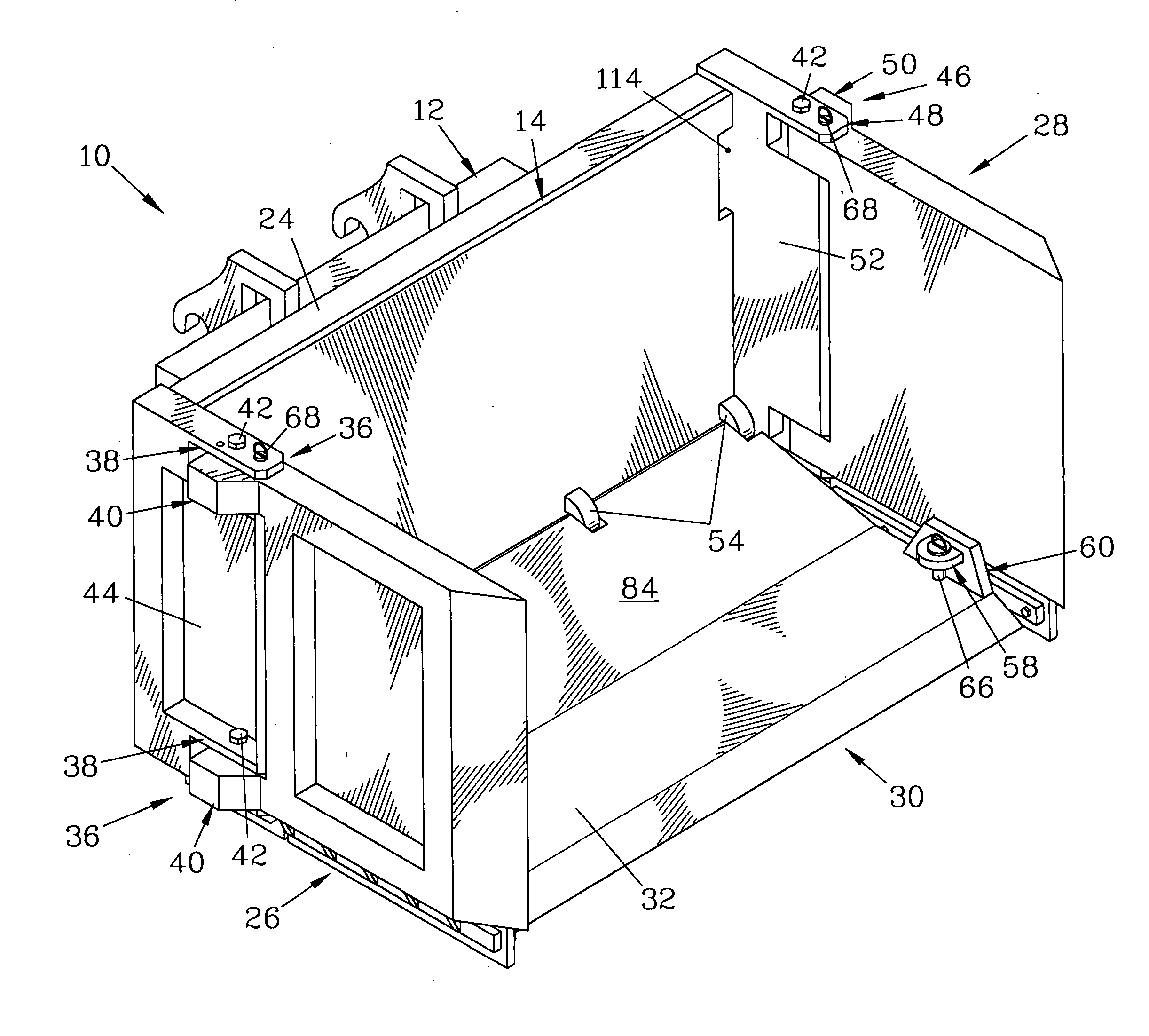
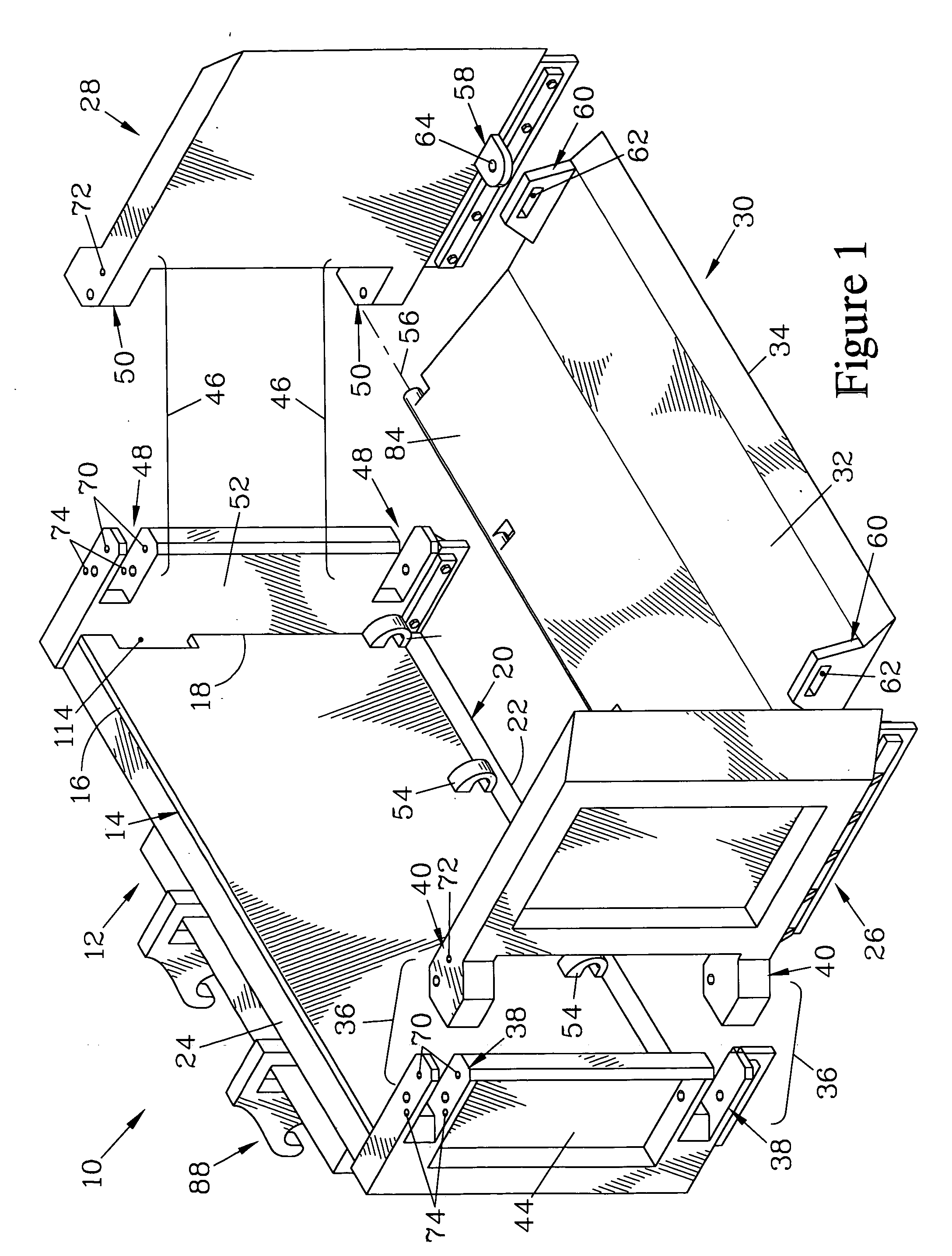
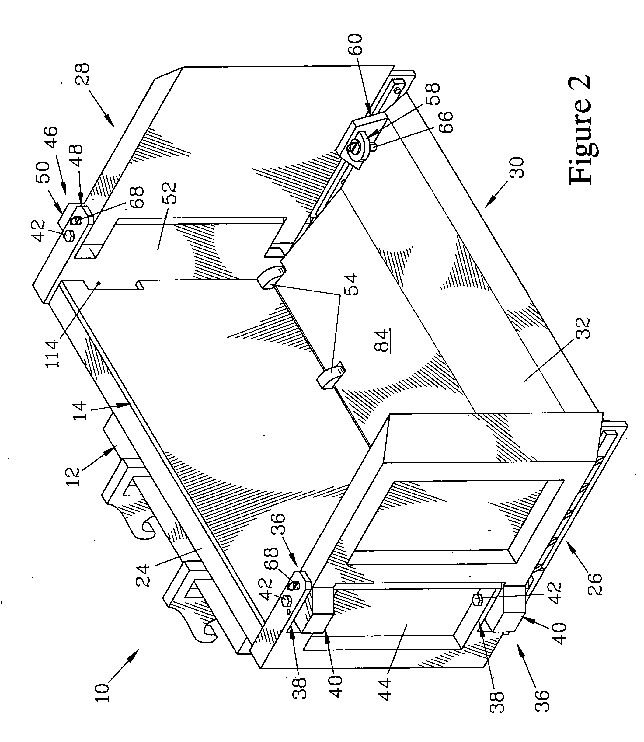
[0048]FIGS. 1 through 6 are various views of a pusher / bucket 10 that forms one embodiment of the present invention. FIG. 1 is a partially exploded isometric view looking from the front toward a back assembly 12 of the pusher / bucket 10. The back assembly 12 has a back plate 14 that terminates in an upper edge 16 and two vertical edges 18 (only one of which is shown), and has a back scraping blade 20 which terminates in a back scraping edge 22 resiliently attached with respect to the back plate 14. The back plate 14 in turn is mounted on a back frame 24 to provide rigidity to the back plate 14 without unduly increasing the overall weight of the pusher / bucket 10.

[0049] The pusher / bucket 10 also has a first wing 26, a second wing 28, and a drop blade 30 that has a substantially planar lead region 32 terminating in a beveled cutting edge 34.

[0050] A first pair of hinges 36 is employed to provide pivotal motion between the back plate 14 and the first wing 26. Each of the hinges 36 in tu...


PUM


Abstract

A pusher/bucket has back plate with wings pivotably mounted at either end, and a drop blade pivotably mounted thereto. The drop blade can be secured in a raised position where it is superimposed over the back plate; when in the raised position, the wings can be positioned relative to the back plate to provide a wing plow. The wings can be folded parallel to the back plate, with the raised drop blade residing therebetween. When the wings are normal to the back plate, the drop blade can be secured in a lowered, horizontal position; in this position, the drop blade acts as the bottom of a loading bucket, the sides being formed by the wings and the back plate. A float mechanism allows the pusher/bucket to push material across uneven terrain, and is preferably disabled when the pusher/bucket is configured as a bucket for loading and dumping material.

Description

FIELD OF THE INVENTION [0001] The present invention relates to devices for removing material from ground surfaces, and more particularly for a device which can be configured to push material as well as configured to load and dump material. BACKGROUND OF THE INVENTION [0002] To remove material from large areas, it is desirable to have a large pushing structure to allow the structure to clear a wider swath across the surface. A typical application is the removal of snow from a paved area such as a road, runway, or parking lot. Conventional snow plows, having a wide blade for pushing the snow aside, have classically been used. [0003] More recently, wider structures called “pushers” have been employed. In addition to having a wider blade, pushers include side boards which frequently extend forward on either side of the blade to direct the material forward and reduce spillage to the sides. Pushers are typically mounted to a bucket loader vehicle, either attached to the conventional bucke...

Claims


Application Information

Patent Timeline
Patent Type & Authority Applications(United States)
IPC IPC(8): E01H5/06E02F3/04E02F3/815
CPCE01H5/066E02F3/8155E02F3/40
Inventor OSGOOD, KEVIN R.DAVIS, JAMES H.SMITH, DAVID J. SR.
Owner RALPH L OSGOOD
Why Eureka
Try Eureka