Thermoelectric generator

a generator and thermoelectric technology, applied in the direction of generators/motors, machines/engines, mechanical equipment, etc., can solve the problem of extremely complicated configuration of thermoelectric generators

Inactive Publication Date: 2005-09-08
DENSO CORP +1
View PDF13 Cites 50 Cited by
  • Summary
  • Abstract
  • Description
  • Claims
  • Application Information

AI Technical Summary

Benefits of technology

[0007] The object of the present invention, in view of the above issues, is to provide a thermoelectric generator having multi-layer capable of bringing thermoelectric elements, hot-side heat source portion and cold-side heat source portion in well contact with each other, without heavy configurations.

Problems solved by technology

However, in the above conventional art, the thermoelectric generator has an extremely complicated configuration as a whole, by filling helium gas and by setting the pressurizing means (the bellows).

Method used


Image

  • Thermoelectric generator
  • Thermoelectric generator
  • Thermoelectric generator

Examples


first embodiment

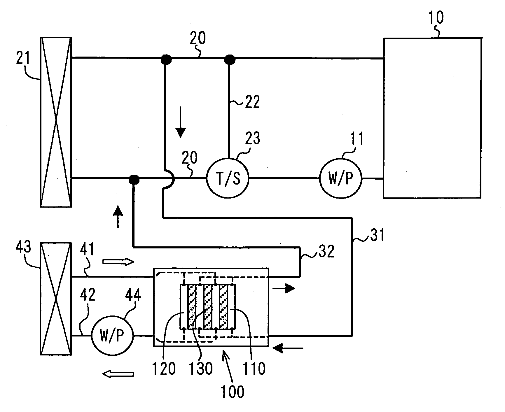
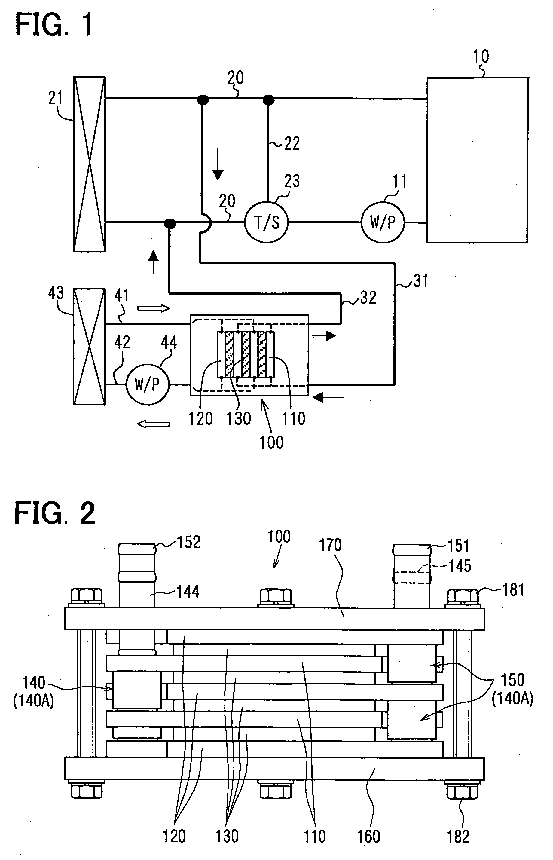
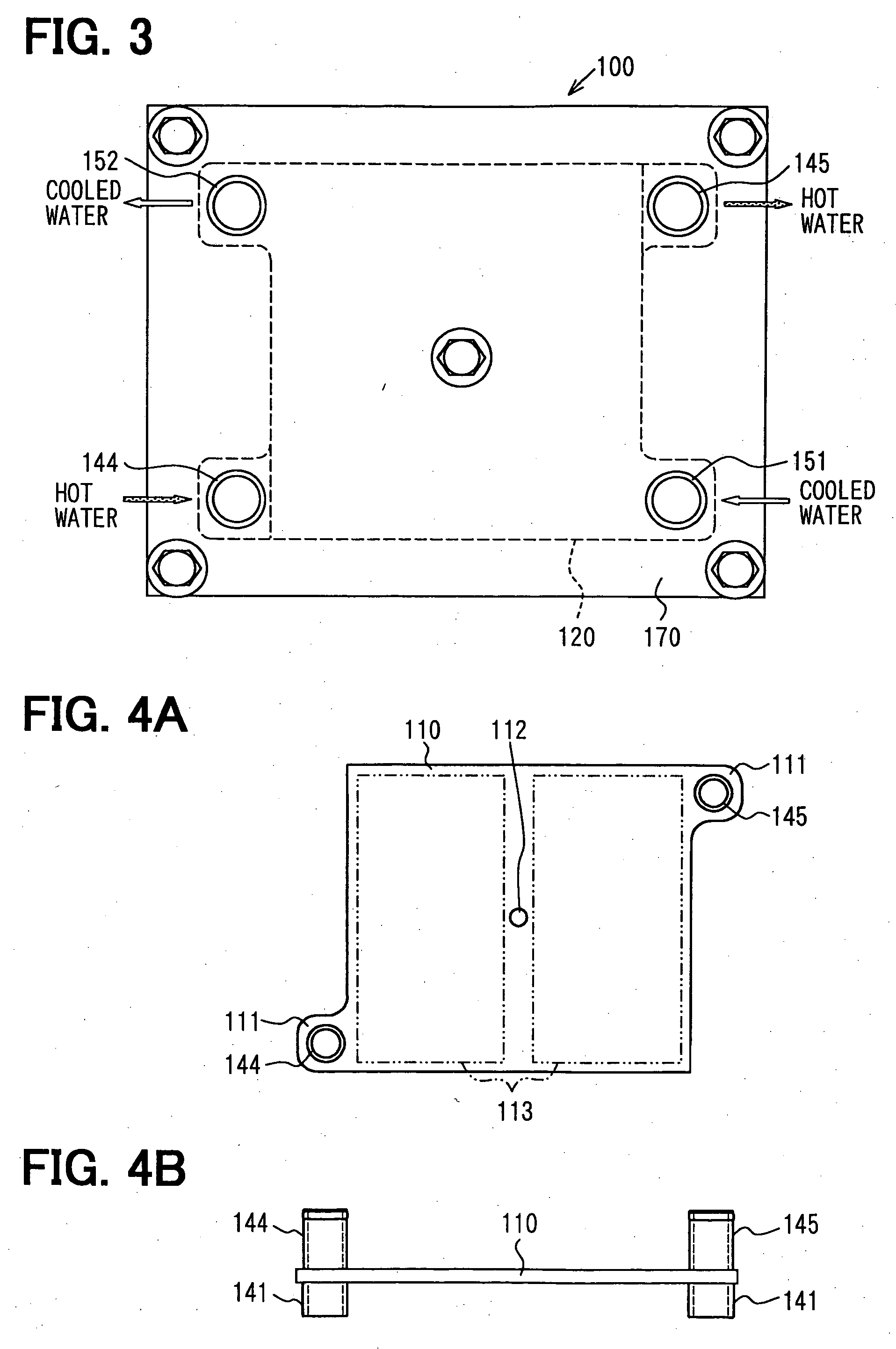
[0028] A thermoelectric generator 100 according to the present invention is applied to a vehicle having a water-cooled engine 10, wherein an electric energy is recovered from a discharged heat energy associated with a cooling of the engine 10. First, a fundamental structure thereof will be described with reference to FIGS. 1 to 8. Here, FIG. 1 is a schematic diagram showing an entire structure including the engine 10. FIGS. 2 and 3 are a front view and a plan view showing an exterior appearance of a thermoelectric generator 100. FIGS. 4 and 5 are plan views and front views showing a high temperature side heat source portions 110. FIGS. 6 and 7 are plan views and front views showing a low temperature side heat source portions 120. FIG. 8 is an exploded diagram showing an assembling way of the high temperature side heat source portions 110, the low temperature side heat source portions 120 and thermoelectric elements 130.

[0029] As shown in FIG. 1, the engine 10 has an engine coolant ...

second embodiment

[0051] A second embodiment of the present invention is shown in FIGS. 9 and 10. The second embodiment has a different configuration from that of the above first embodiment in the respective communicators 140, 150. The second embodiment adopts pipes 141a (corresponding to “pipe” in the present invention) having bellows 142a, which extends and shrinks according to a distance between the both ends of the pipe 141a. The bellows 142a serves as the distance adjuster 140A.

[0052] As shown in FIG. 10, a stack of the heat source portions 110, 120 is formed by alternately stacking the cold-side heat source portions 120 and the hot-side heat source portions 110, disposing the pipes 141a between the respective heat source portions 110, 120 and blazing them integrally. In the stack, the clearances between both of the heat source portions 110, 120 are set to be larger than a thickness of the thermoelectric device 130.

[0053] Here, the hot-side heat source portions 140 (at left side in FIG. 10) pa...

third embodiment

[0057] A third embodiment of the present invention is shown in FIG. 11. The third embodiment, in contrast to the first embodiment, a stack of the hot-side heat source portions 110, the cold-side heat source portions 120 and the thermoelectric elements 130 sandwiched between the lower plate 160 and the upper plate 170 is enclosed by a vacuum container 190 that keeps an internal space thereof to an approximately vacuum state.

[0058] A heat transfer is reduced in a vacuum compared to that in the air, so as to reduce the temperature difference between the both heat source portions 110, 120 caused by the thermal dissipation from the hot-side heat source portions 110 to the outside and by the thermal absorption by the cold-side heat source portions 120.

[0059] When the vacuum container 190 is not adopted and the cold-side heat source portions 120 are colder than the outer air, the water vapor in the air is condensed on the surface of the cold-side heat source portions 120, which may cause...


PUM


Abstract

A thermoelectric generator has a plurality of hot-side heat source portions, a plurality of cold-side heat source portions, a thermoelectric element, a hot-side communicator and a cold-side communicator. Hot fluid flows in the plurality of hot-side heat source portions, and cold fluid colder than the hot fluid flows in the plurality of cold-side heat source portions. The heat source portions are alternately stacked in such a manner of interposing the thermoelectric element between the hot-side heat source portion and the cold-side heat source portion. The hot-side communicator communicates the hot-side heat source portions, and the cold-side communicator communicates the plurality of cold-side heat source portions. Each of the hot-side communicator and the cold-side communicator has a distance adjuster for adjusting distances between the hot-side heat source portions and the cold-side heat source portions so as to bring them in contact with the thermoelectric elements in the stacking direction thereof.

Description

CROSS REFERENCE TO RELATED APPLICATION [0001] This application is based upon and claims the benefit of priority of Japanese Patent Application No. 2004-061383 filed on Mar. 4, 2004, the content of which is incorporated herein by reference. FIELD OF THE INVENTION [0002] The present invention relates to a thermoelectric generator that generates an electric power by Seebeck effect applying a temperature difference to a thermoelectric element. BACKGROUND OF THE INVENTION [0003] JP-10-136672-A discloses a conventional thermoelectric generator having a plurality of heat exchangers for heating and for cooling alternately stacked and thermoelectric generation modules disposed between the heat exchangers. The heat exchangers are communicated to each other by an emission gas supply pipe at one end side thereof and by an emission gas emission pipe at another end side thereof so that the emission gas flows through all of the heat exchangers. Specifically, each of the emission gas supply pipe an...

Claims


Application Information

Patent Timeline
Patent Type & Authority Applications(United States)
IPC IPC(8): F01P3/18F01N5/02H01L35/30H01L35/32H02N11/00
CPCH01L35/30H10N10/13
Inventor YAMAGUCHI, HIROOYAMANAKA, YASUTOSHIINAOKA, HIROYAMORI, RENTARO
Owner DENSO CORP
Why Eureka
Try Eureka