Thin film piezoelectric actuator

a piezoelectric actuator and thin film technology, applied in the direction of relays, generators/motors, device material selection, etc., can solve the problems of low melting point, high vapor pressure, and inability to easily apply to general consumer appliances

Inactive Publication Date: 2005-09-08
KK TOSHIBA
View PDF4 Cites 75 Cited by
  • Summary
  • Abstract
  • Description
  • Claims
  • Application Information

AI Technical Summary

Problems solved by technology

At present, from the problem that the driving voltage is high, it is not easily applied to general consumer appliances.
However, to produce a highly efficient piezoelectric thin film of PZT series by the thin film art, problem arise that in a lead series material, the melting point thereof is low and the vapor pressure thereof is high, and the composition control in the film deposition process is difficult, and the lead series material cannot be used in a general semiconductor manufacturing line.
When a thin film having a structure of such a high aspect ratio is prepared, the ...

Method used


Image

  • Thin film piezoelectric actuator
  • Thin film piezoelectric actuator
  • Thin film piezoelectric actuator

Examples


first embodiment

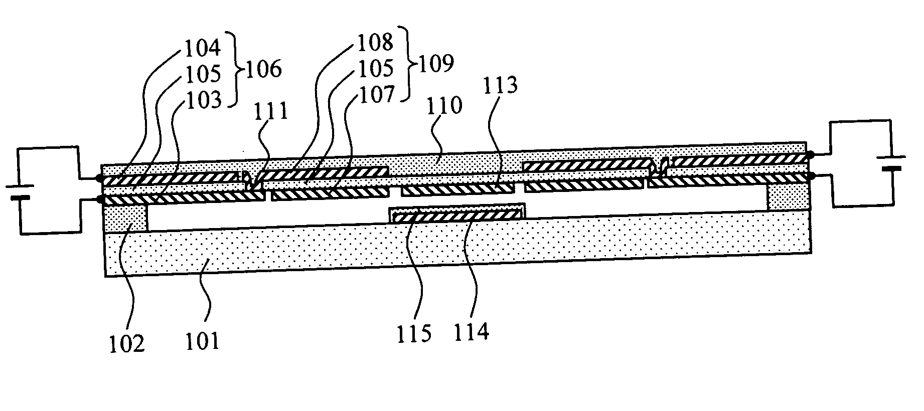
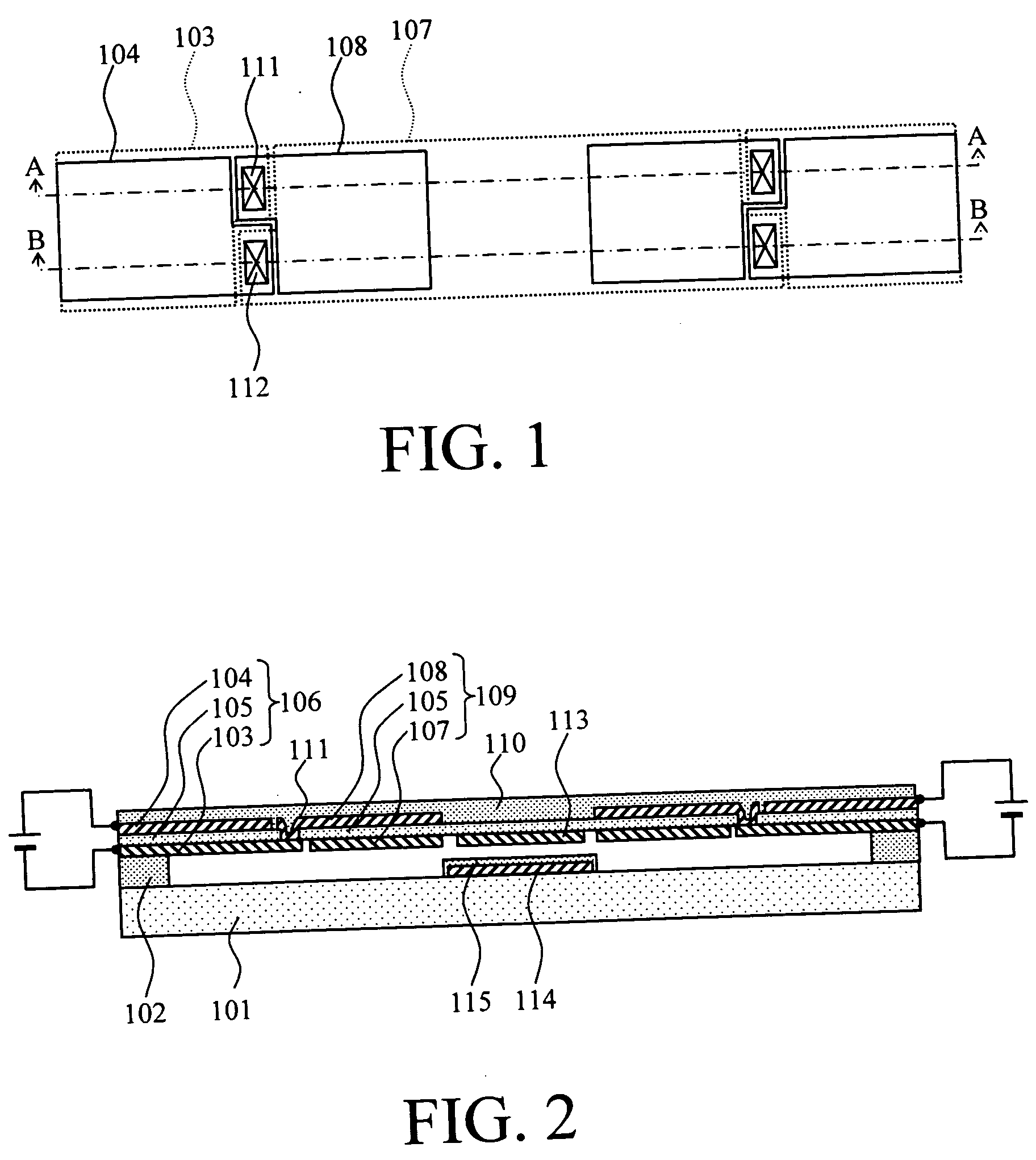
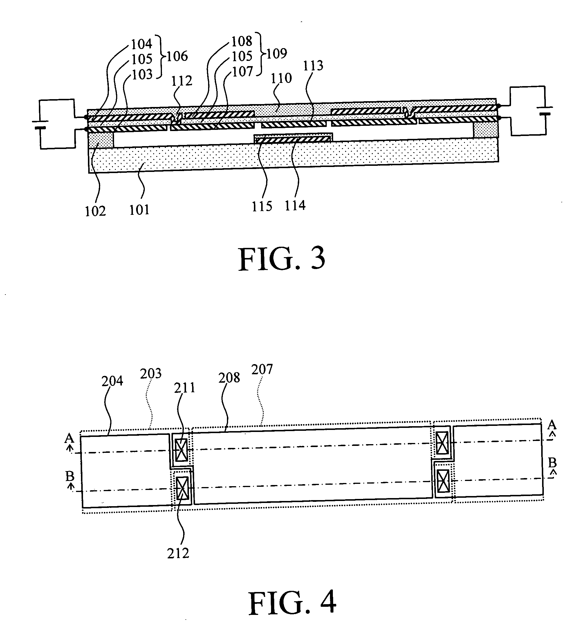
[0068]FIG. 1 is a plan view of a variable capacitor applying the thin film piezoelectric actuator of a double-clamped beam structure of the first example of the present invention. Further, FIG. 2 is a cross sectional view of the line A-A of the plan view shown in FIG. 1, and FIG. 3 is a cross sectional view of the line B-B. In the plan view shown in FIG. 1, to avoid complication, only the upper and lower electrodes and via holes are shown.

[0069] As shown in FIGS. 2 and 3, a first driving part 106 in contact with anchors 102 on both sides provided on a substrate 101, which is composed of first upper and lower electrodes 103 and 104 and a first piezoelectric film 105 held by them, a second driving part 109 provided in the neighborhood of the first driving part 106, which is composed of second upper and lower electrodes 107 and 108 and the piezoelectric film 105 held by them, and a support film 110 for forming a bimorph structure are provided. The support film 110 may be provided unde...

second embodiment

[0104] Next, as the second embodiment of the present invention, a thin film piezoelectric actuator in which the end of the electrode provided under the piezoelectric film is tapered will be explained.

[0105]FIG. 18 is a plan view of the thin film piezoelectric actuator of a cantilever beam structure of the fifth example of the present invention.

[0106] Further, FIG. 19 is a cross sectional view of the line A-A shown in FIG. 18. Further, in the plan view of FIG. 18, to avoid complication, only the upper and lower electrodes and via holes formed in the piezoelectric film are shown.

[0107] As shown in FIGS. 18 and 19, a first driving part 46 in contact with an anchor 42 provided on a substrate 40, which is composed of a piezoelectric film 44 held by first upper and lower electrodes 45 and 43, a second driving part 49 provided in the neighborhood of the first driving part, which is composed of the piezoelectric film 44 held by second upper and lower electrodes 48 and 47, and a support f...


PUM


Abstract

A thin film piezoelectric actuator comprises a driving part at least one end of which is supported by an anchor portion. The driving part includes: a piezoelectric film, a first lower electrode provided under a first region of the piezoelectric film, a second lower electrode provided under a second region different from the first region of the piezoelectric film, a first upper electrode provided opposite to the first lower electrode on the piezoelectric film, a second upper electrode provided opposite to the second lower electrode on the piezoelectric film, a first connection part that electrically connects the first lower electrode and the second upper electrode via a first via hole formed in the piezoelectric film, and a second connection part that electrically connects the second lower electrode and the first upper electrode via a second via hole formed in the piezoelectric film.

Description

CROSS-REFERENCE TO RELATED APPLICATIONS [0001] This application is based upon and claims the benefit of priorities from the prior Japanese Patent Application Nos. 2004-34984 and 2005-3370, filed on Feb. 12, 2004 and Jan. 11, 2005; the entire contents of which are incorporated herein by reference. BACKGROUND OF THE INVENTION [0002] The present invention relates to a thin film piezoelectric actuator and more particularly to a thin film piezoelectric actuator which can be favorably applied to a micro-electro-mechanical system (MEMS), can be easily controlled, and uses a piezoelectric thin film driven at a low voltage over a wide range. [0003] In a microswitch or a variable capacitor by a conventional MEMS art, electrostatic force is mainly used as driving force. The MEMS actuator using the electrostatic force has an advantage that a very simple operation mechanism only applying a driving voltage to a pair of electrodes across a space is preferably used (for example, “Smart Structure an...

Claims


Application Information

Patent Timeline
IPC IPC(8): H01G7/06H01L41/09H01L41/053H01L41/08H01L41/18H01L41/187H01L41/22H01L41/29H01L41/316
CPCH01G7/06H01L41/094H01L41/0933H01H2057/006H10N30/2041H10N30/2042
Inventor KAWAKUBO, TAKASHIOHARA, RYOICHIONO, TOMIONAGANO, TOSHIHIKONISHIGAKI, MICHIHIKOYASUMOTO, TAKAAKIABE, KAZUHIDESANO, KENYA
Owner KK TOSHIBA
Why Eureka
Try Eureka