Autoilluminating rechargeable lamp system

a rechargeable lamp and auto-illuminating technology, applied in the field of illumination, can solve the problems of undesirable wax build-up and affecting the appearance of candles,

Inactive Publication Date: 2005-09-08
HELEN OF TROY LIMITED
View PDF13 Cites 38 Cited by
  • Summary
  • Abstract
  • Description
  • Claims
  • Application Information

AI Technical Summary

Benefits of technology

[0005] It is accordingly a general object of the present invention to disclose a rechargeable lamp system that provides candle-like lighting for indoor or outdoor use that avoids the problems associated with candles.
[0014] In one presently preferred embodiment, each luminary of the set of luminaries includes a diffusor releasably mounted to a base. A light support carried by the base allows replacement of the light emitting element and a rechargeable battery compartment carried by the base allows replacement of the rechargeable battery. In the presently preferred embodiments, the light support and battery compartment are adapted to allow manual light element and rechargeable battery replacement, and the diffusor is manually releasably mounted to the base, although light mechanical action could be employed to provide ease of light element and rechargeable battery replacement without departing from the inventive concepts. Multiple light emitting elements and corresponding supports may be provided for light animation effects.

Problems solved by technology

While their utilitarian and aesthetic advantages are well-known, candles suffer from an undesirable self-consumption, needing to be replaced when used-up; produce smoke especially when snuffed, which may foul the air; require vigilant attendance to mitigate an ever-present fire hazard; are susceptible to being extinguished by gusts of air when used outdoors or moved around; and may give rise to undesirable wax build-up, which in many instances needs removed from candle support members or underlying structures.

Method used


Image

  • Autoilluminating rechargeable lamp system
  • Autoilluminating rechargeable lamp system
  • Autoilluminating rechargeable lamp system

Examples


Embodiment Construction

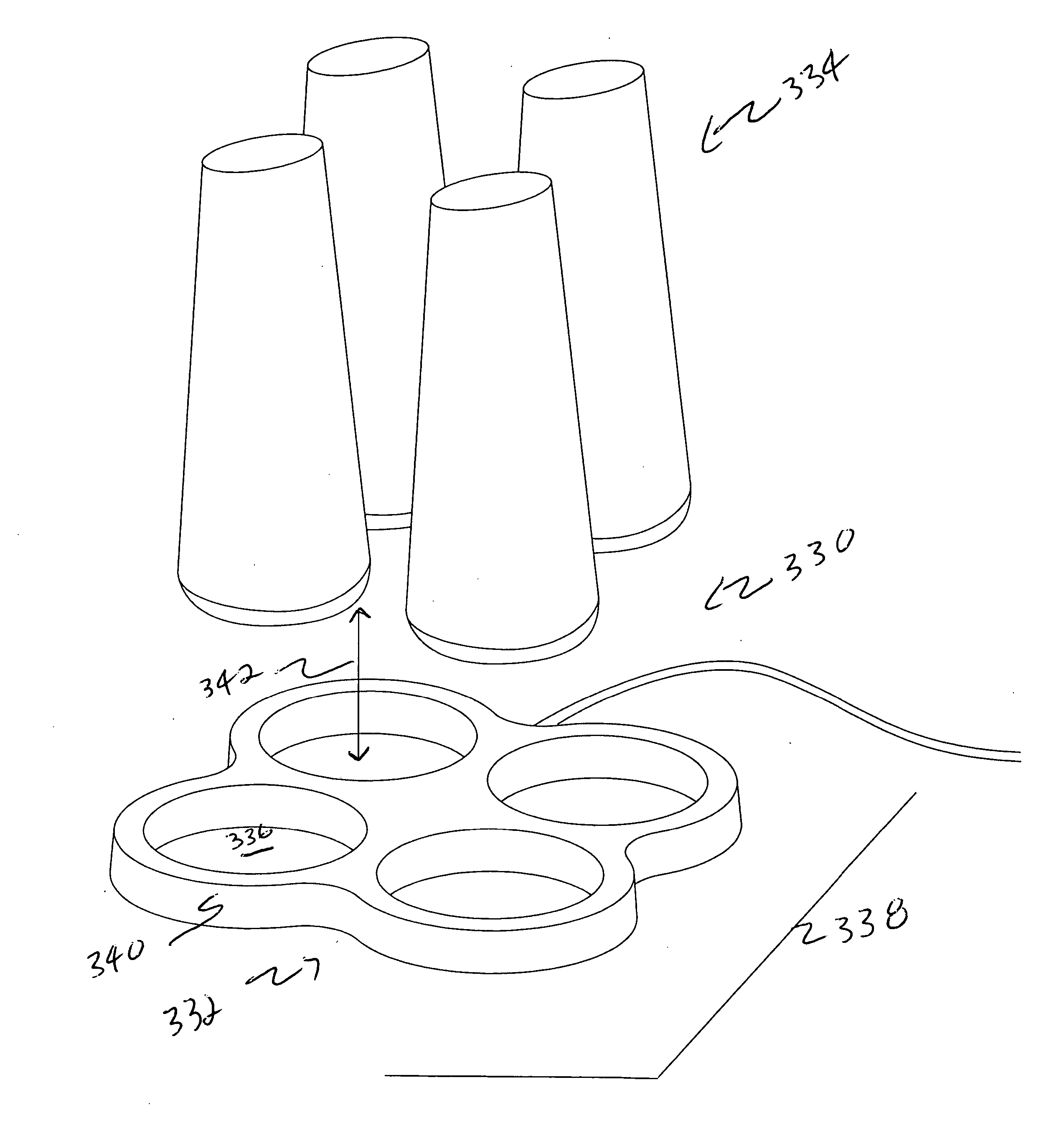
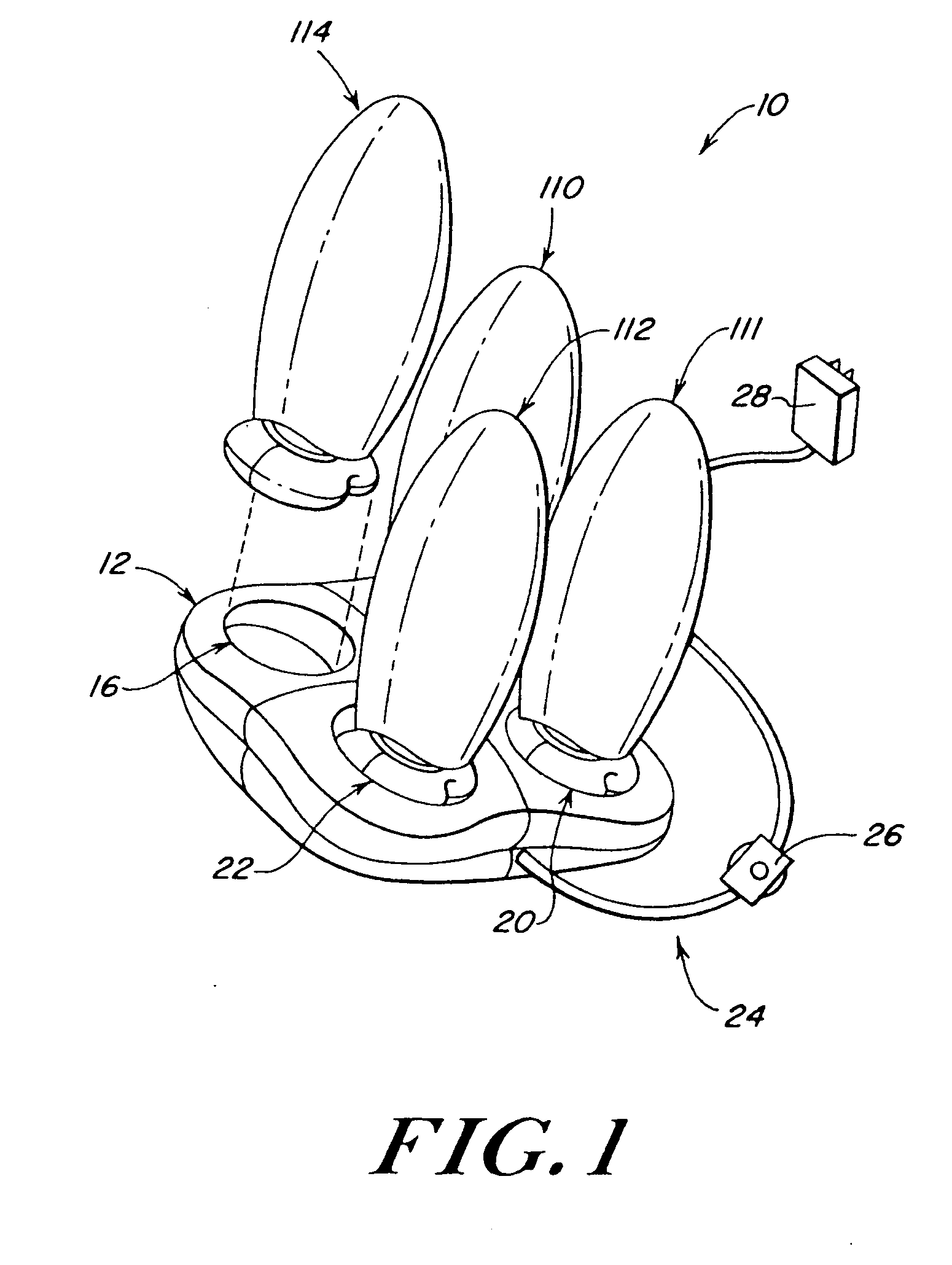
[0039] Referring now to FIG. 1, reference numeral 10 generally refers to the rechargeable lamp system of the present invention. Lamp system 10 comprises a charging stand 12 and a plurality of lamp modules 110, 111, 112 and 114.

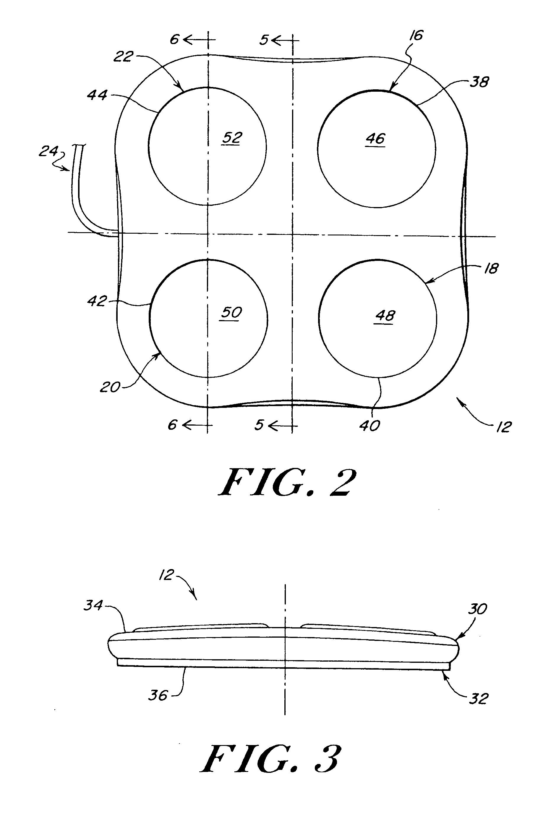
[0040] As shown in FIGS. 1 and 2, stand 12 comprises slots 16, 18, 20 and 22 which are each adapted to removably receive one of said lamp modules 110, 111, 112 and 114. Slots 16, 18, 20 and 22 each include a respective cylindrical wall 38, 40, 42, and 44 and a substantially planar floor 46, 48, 50 and 52.

[0041] A power cord 24 having an inline power switch 26 and a “wall-block” style transformer provides power to charging stand 12 via ordinary 120-volt household current. In alternate embodiments, the transformer may be dispensed with.

[0042] As will be described in greater detail herein, each of modules 110, 111, 112 and 114 is battery-powered and designed to be charged by magnetic induction when placed in a respective one of slots 16, 18, 20 and 22. Modules...


PUM

PropertyMeasurementUnit
voltageaaaaaaaaaa
currentaaaaaaaaaa
chargeaaaaaaaaaa

Abstract

An autoilluminating rechargeable lamp system includes a set of one or more self-standing rechargeable lighting fixtures (luminaries) removably supported on a recharging and support member. The luminaries each include a light diffusor that may resemble a-that turn on when removed from the recharging and support member. The luminaries may also turn on when power to the recharging and support member is turned off, turning the luminaries on automatically as during a power failure. The luminaries may each be inductively coupled to the recharging and support member, which enables to provide an aesthetically pleasing interface free of electrical contacts.

Description

CROSS-REFERENCE TO RELATED APPLICATIONS [0001] The present invention is a continuation-in-part of allowed co-pending U.S. utility patent application Ser. No. 10 / 292,007, which is a continuation-in-part of U.S. utility patent application Ser. No. 09 / 885,848, U.S. Pat. No. 6,479,965, of the same inventive entity as herein, both incorporated herein by reference.FIELD OF THE INVENTION [0002] The present invention is drawn to the field of illumination, and more particularly, to a novel rechargeable lamp system. BACKGROUND OF THE INVENTION [0003] Candles may be moved and placed to provide illumination and / or ambience. While their utilitarian and aesthetic advantages are well-known, candles suffer from an undesirable self-consumption, needing to be replaced when used-up; produce smoke especially when snuffed, which may foul the air; require vigilant attendance to mitigate an ever-present fire hazard; are susceptible to being extinguished by gusts of air when used outdoors or moved around; ...

Claims


Application Information

Patent Timeline
Patent Type & Authority Applications(United States)
IPC IPC(8): F21L2/00F21L4/02F21L4/08F21S9/02F21V23/02F21V23/04H02J7/00H05B39/00
CPCF21L2/00F21L4/08F21S9/022F21S10/04F21V23/02F21V23/0442F21V3/0445F21Y2101/02H02J7/0044H02J7/025H02J9/02H05B39/00F21V3/02F21V23/06F21Y2115/10F21V3/0625H02J50/40H02J50/10
Inventor BARBEAU, STEFANE E.SMITH, DUANE B.DRUM, DONALD
Owner HELEN OF TROY LIMITED
Why Eureka
Try Eureka