Bidirectional power conversion with multiple control loops

a power conversion and control loop technology, applied in the direction of dynamo-electric machines, braking systems, electric variable regulation, etc., can solve the problems of inopportunely large amount of switches present, and the true bidirectional power conversion is not realized, so as to reduce the number of switches used in fabricating the circuit of the present invention, the volume, cost, complexity, and the size of the bidirectional power converter

Inactive Publication Date: 2005-09-08
ANALOG DEVICES INT UNLTD
View PDF2 Cites 54 Cited by
  • Summary
  • Abstract
  • Description
  • Claims
  • Application Information

AI Technical Summary

Benefits of technology

[0006] The present invention provides systems and methods for providing bidirectional power conversion using a single converter and controller for power routing. Through the use of only a single converter and controller, the amount of switches used in fabricating the circuit of the present invention is significantly reduced. In fact, the number of necessary switches may be nearly halved. Moreover, the volume, cost, complexity, and size of a bidirectional power converter in accordance with the principles of the present invention may also be nearly halved.
[0007] In addition to the above, further consideration relating to bidirectional power conversion should preferably also be given to the need for relatively high efficiency, which is measured as a ratio of the power output to the power input. Higher efficiency can be achieved by reducing system losses, and can enable extended battery operating time. The present invention therefore combines power routing and power conversion, and in doing so, eliminates the necessity for several switches and reduces total power (I2R) losses. Furthermore, the power supply switching techniques used in accordance with the principles of the present invention provide additional efficiency in bidirectional power conversion systems.

Problems solved by technology

Power routing and power conversion processes may be found, for example, in uninterruptible power systems, next-generation automotive electrical systems, redundant battery systems for computers, telecommunications equipment and portable electronic devices.
In prior systems, truly bidirectional power conversion is not realized.
The result of using multiple power converters in addition to additional logic for the purpose of routing in prior systems is that the amount of switches present is inopportunely large.

Method used


Image

  • Bidirectional power conversion with multiple control loops
  • Bidirectional power conversion with multiple control loops
  • Bidirectional power conversion with multiple control loops

Examples


Embodiment Construction

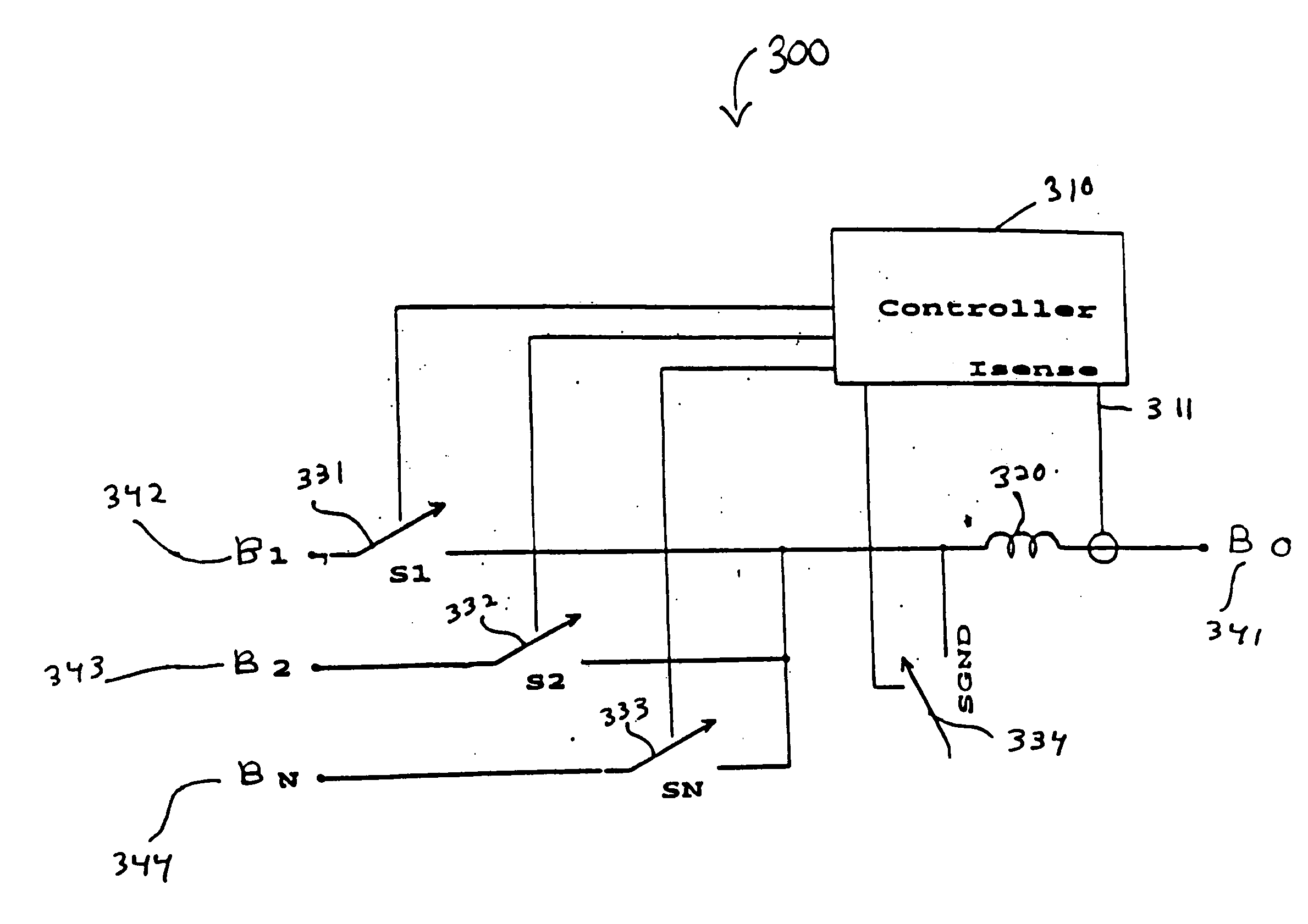
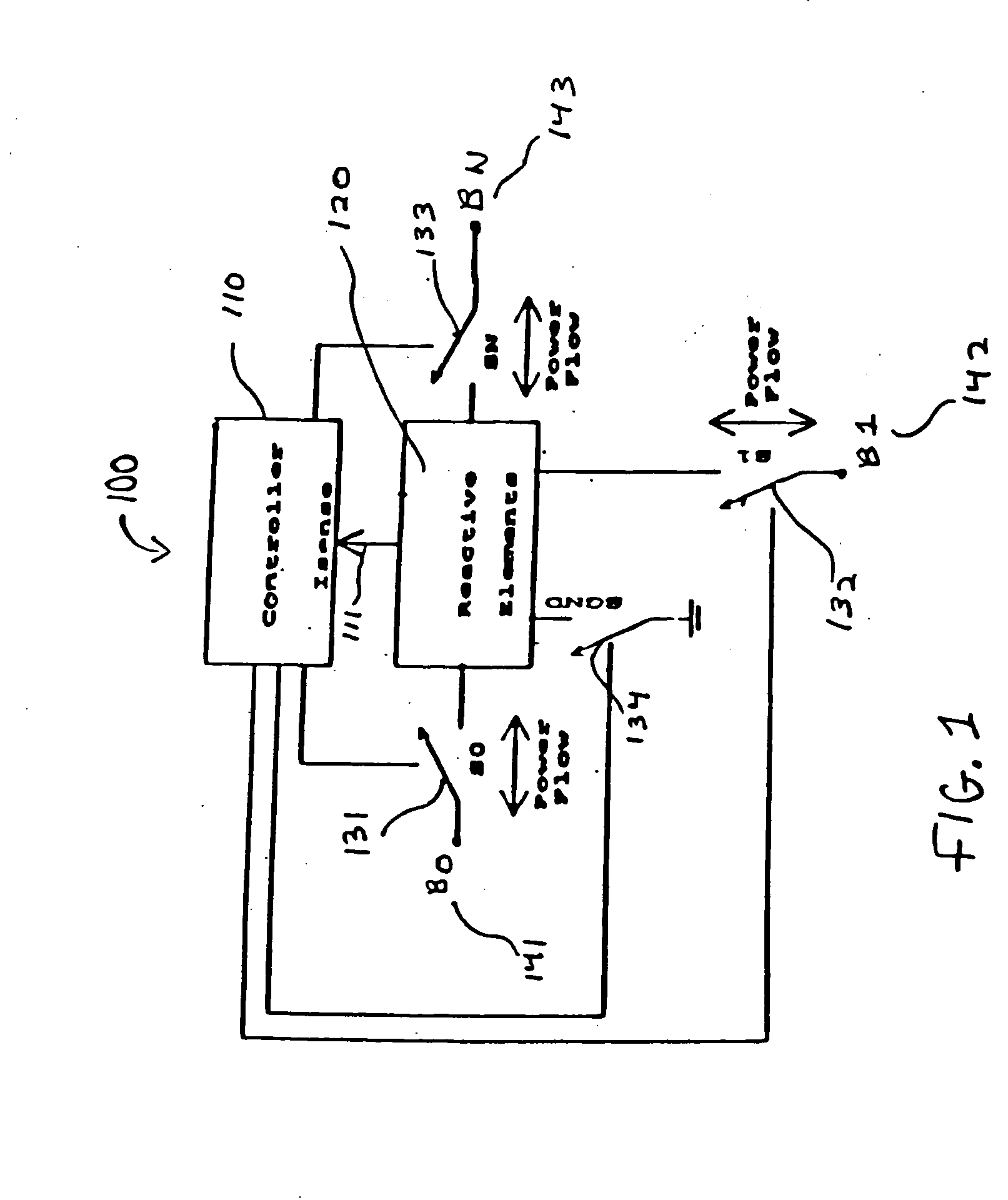
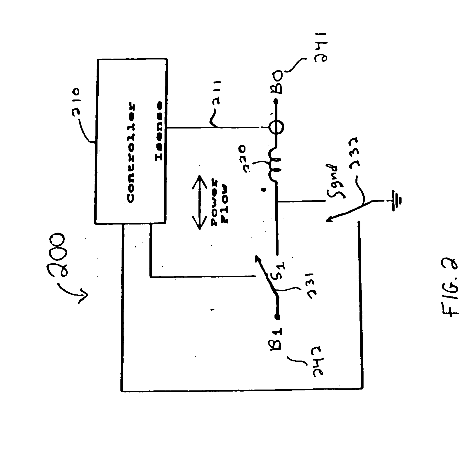
[0024]FIG. 1 shows a simplified schematic 100 of a bidirectional power converter in accordance with the principles of the present invention. Schematic 100 comprises controller 110, reactive elements 120, switches S0131, S1132, SN 133 and SGND 134 and power buses B0141, B1142 and BN143. In schematic 100, as well as in the following circuits to be presented in accordance with the principles of the present invention, the switches shown are generally single-pole, single-throw switches. In practice, these switches may be realized, for example, by using semiconductor devices such as power metal-oxide semiconductor field effect transistors (MOSFETs), insulated gate bipolar transistors (IGBTs), bipolar junction transistors (BJTs), thyristors or other suitable devices.

[0025] Switch S0131 of FIG. 1 is used to control the flow of power between bus B0141 and reactive elements 120. Similarly, switches S1132 and SN 133 control the power flow between bus B1142 and reactive elements 120, and betwe...


PUM


Abstract

Bidirectional power conversion systems provide the ability to change power attributes to and from a component. Current bidirectional power conversion systems use a unidirectional power converter for each direction. The integration of the two normally independent power converters results in a bidirectional power converter with nearly half the size, weight, volume, cost and complexity. Described are embodiments of bidirectional power conversion systems that allow power transfer between two or more components without requiring the use of separate unidirectional power converters.

Description

BACKGROUND OF THE INVENTION [0001] This invention relates to systems and methods for producing bidirectional power conversion. More specifically, this invention relates to circuits and methods for creating a truly bidirectional power converter with multiple control loops and power routing. [0002] As the need for smaller and more intricate integrated circuits surfaces, so does the need for smaller power routing and power conversion processes. Power routing and power conversion processes may be found, for example, in uninterruptible power systems, next-generation automotive electrical systems, redundant battery systems for computers, telecommunications equipment and portable electronic devices. [0003] Bidirectional power conversion provides the ability to change power attributes to and from a component. Bidirectional power conversion may be found in portable devices such as cell phones and Personal Digital Assistants (PDAs) that contain rechargeable batteries. These DC rechargeable ba...

Claims


Application Information

Patent Timeline
Patent Type & Authority Applications(United States)
IPC IPC(8): G05F1/70H02K7/02H02M3/158H02M3/335H02M5/42
CPCG05F1/70H02M3/33584H02M3/1582
Inventor HACK, THOMAS P.DOBKIN, ROBERT C.
Owner ANALOG DEVICES INT UNLTD
Why Eureka
Try Eureka