
Adjustable convergence device for a projector and projector equipped with such a convergence device

a technology of convergence device and projector, which is applied in the direction of picture reproducers, television systems, instruments using projection devices, etc., can solve the problems of difficult correction, affecting the accuracy of the adjustment, and the typical mounting position of light modulators, so as to achieve precise and accurate adjustments. , the effect of short tim

Active Publication Date: 2005-09-08
BARCO NV
View PDF1 Cites 29 Cited by
  • Summary
  • Abstract
  • Description
  • Claims
  • Application Information

AI Technical Summary

Benefits of technology

[0016] It is therefore an objective of the invention to provide an adjustable convergence device that allows for rectification of the convergence in a relatively short time, typically within a few minutes, allowing for very precise and accurate adjustments to be performed by a person with basic skills.

Problems solved by technology

A disadvantage of this kind of convergence device is that tightening of these screws affects the alignment of the plate, therefore requiring up to eight iterations to fix the plate in the desired position.
Another disadvantage of present systems is that the light modulators are typically mounted with their edges forming an angle with the vertical.
In order to shift the projected image in a vertical direction on the projection screen, the concerned light modulator has to be moved in an angled direction, making corrections even more difficult.
Another disadvantage is that access to the adjustment screws is often very difficult.
This is further complicated by building projectors with an hermetically sealed housing.

Method used


Image

  • Adjustable convergence device for a projector and projector equipped with such a convergence device
  • Adjustable convergence device for a projector and projector equipped with such a convergence device
  • Adjustable convergence device for a projector and projector equipped with such a convergence device

Examples


Embodiment Construction

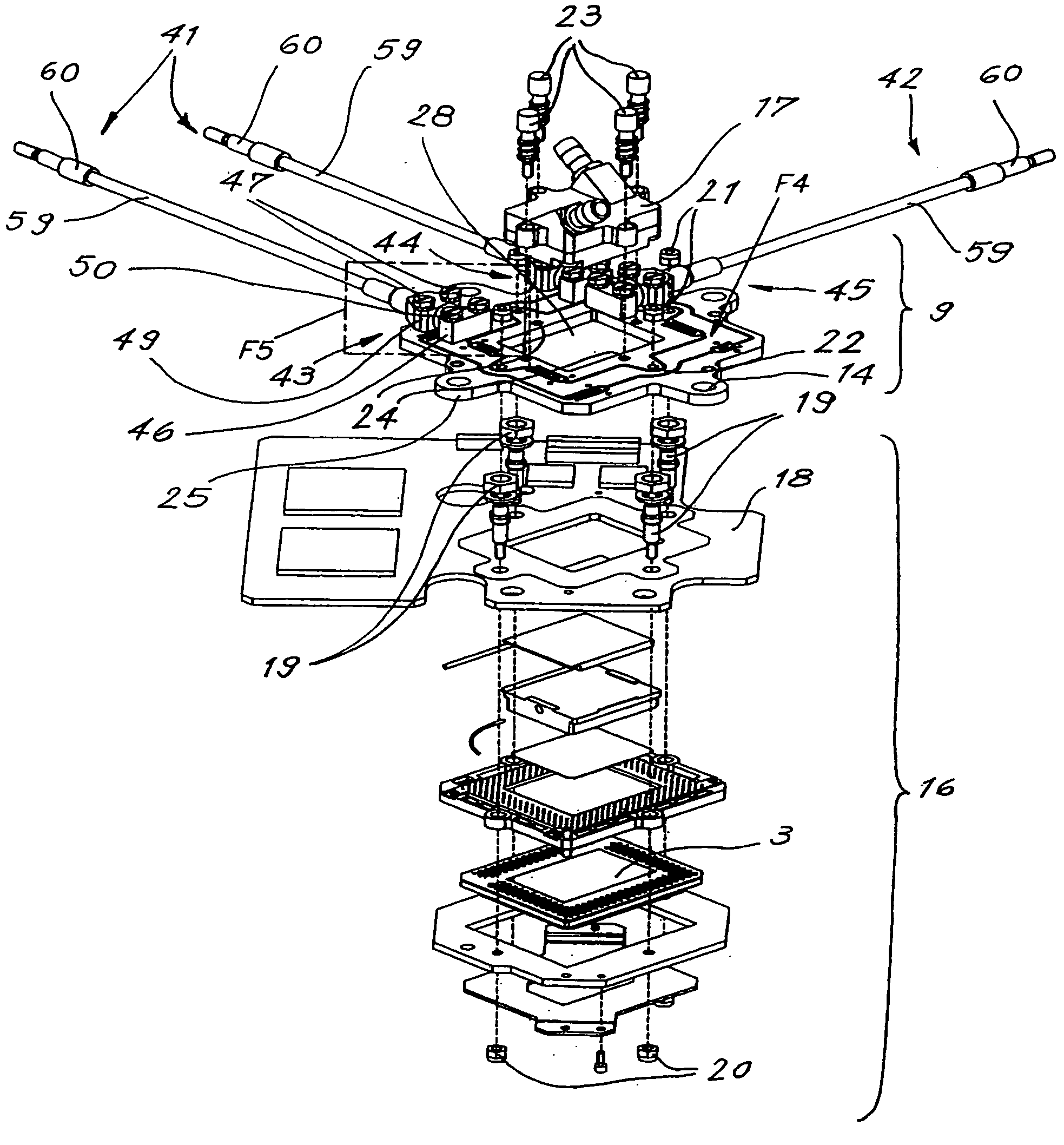
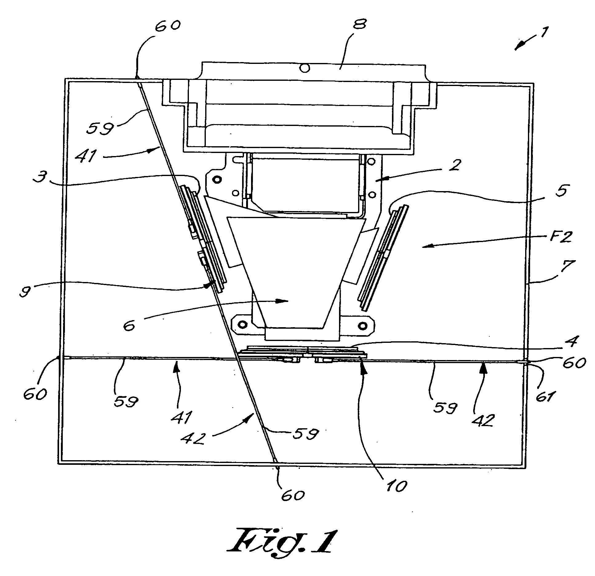
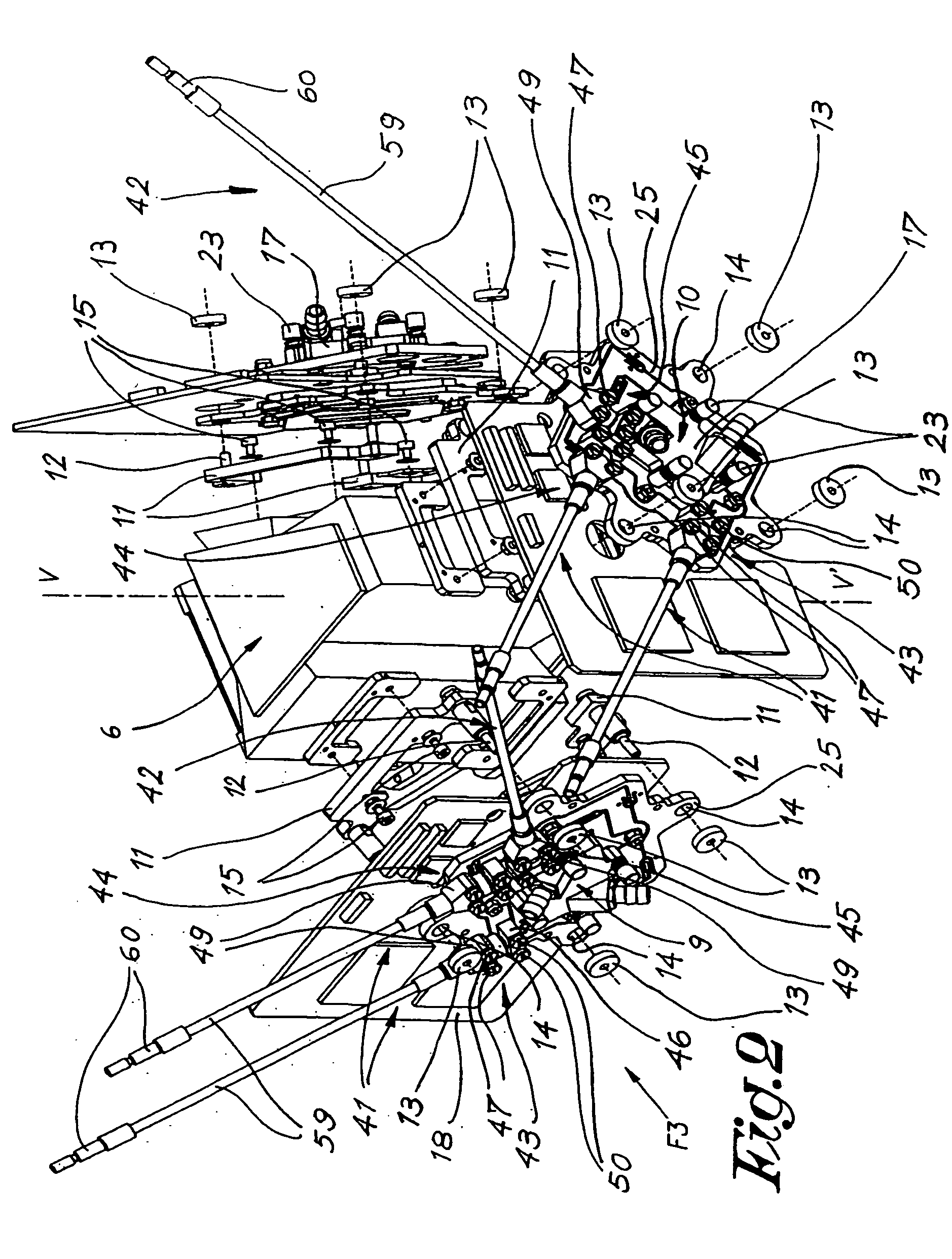
[0035] The projector 1 represented in FIGS. 1 and 2 mainly comprises a so called engine consisting of a frame 2, three light modulators 3, 4 and 5 mounted on said frame 2; an optical system 6 composed of a plurality of lenses, prisms and the like, and electronic components which are not represented, which engine is enclosed in a housing 7, preferably an hermetically sealed housing 7, with a projection window 8.

[0036] The light modulators 3, 4, 5 are well known devices such as digital mirror devices (DMD), each of which are used to generate a digital image in a different color, for example a red, green and a blue image respectively, these being guided in a known manner through the optical system 6 and through the window 8 of the housing and projected in superposition on a projection screen which is not represented.

[0037] The light modulator 5, for example the blue light modulator, is in this case fixed to the frame, whilst each of the two other light modulators 3 and 4, for example...


PUM


Abstract

An improved adjustable convergence device for adjusting the position of a pixel light modulator of a projector comprising at least two such light modulators mounted on the frame of the projector, said convergence device comprising a plate assembly which is fixed on said supporting frame and which supports the light modulator to be adjusted, wherein said plate assembly is composed of at least two plate elements, respectively a plate element which is fixed to the supporting frame and a plate element on which the light modulator is fixed, whereby these plate elements are connected to each other by means of at least one elastic joint and whereby at least first self-locking adjusting means are provided for transmitting a force in an adjusting direction between these plate elements in order to adjust the relative position between said plate elements.

Description

FIELD OF THE INVENTION [0001] The present invention relates to a projector which is equipped with two or more pixel light modulators, such as DMD (digital mirror devices), LCOS, LCD or the like, whereby each light modulator generates a separate image with different colored light, usually red, green and blue light, and whereby these separate images are projected through a system of lenses and prisms onto a projection screen to form a superposed full color single image. [0002] For good quality of the final image, it is essential that the separate light modulators are well aligned with respect to one another, generally in six degrees of freedom, namely three translations following the X, Y and Z directions of a rectangular coordinate system and the corresponding three rotations around these axes. The X and Y translations being situated in the plane of the concerned light modulator, and Z translation in the direction of the optical axis of the light modulator perpendicular to the plane ...

Claims


Application Information

Patent Timeline
IPC IPC(8): H04N5/74H04N9/28H04N9/31
CPCG03B33/06H04N9/3197H04N9/317
Inventor VON PONCET, ALEXANDERVAN DEN BOSSCHE, BART
Owner BARCO NV
Learn More