Digital device configuration and method

a technology of digital devices and configuration methods, applied in the field of digital device architecture, can solve the problems of 32 mb being a relatively limited amount of storage, portable device owners being forced to frequently reload flash memory cards, and the current cost of flash memory cards is somewhat prohibitiv

Inactive Publication Date: 2005-09-08
CORNICE
View PDF64 Cites 9 Cited by
  • Summary
  • Abstract
  • Description
  • Claims
  • Application Information

AI Technical Summary

Problems solved by technology

Unfortunately, several problems are associated with this solution, as will be described.
One problem seen with regard to the flash memory solution resides in the fact that 32 MB is, in itself, a somewhat limited amount of storage.
Otherwise, the portable device owner may be forced to frequently reload the flash memory card via a personal computer or otherwise be subjected, for example, to listening to a quite limited music selection in the instance of an MP3 player.
Moreover, the cost of flash memory cards is currently somewhat prohibitive.
While the Microdrive brings improvement in data capacity, as of this writing, the cost of the Microdrive is quite high in terms of megabytes per dollar and absolute cost when compared to such costs in conventional drives.
It is submitted that this absolute cost, in and by itself, will prove to be a significant barrier with regard to broad-based use of the product.
Under operational circumstances, unfortunately, hard disk drives are generally quite susceptible to mechanical shock events, for example, during the time that the head or sensing assembly is actually accessing the rotating media.
Consequences of a mechanical shock event occurring at precisely the most inopportune time include potential drive failure.
For instance, a drive may fail when subjected to a 175 G event during an access.
For example, commands issued through levels or layers of protocol higher than the native code are particularly inflexible.

Method used


Image

  • Digital device configuration and method
  • Digital device configuration and method
  • Digital device configuration and method

Examples


Embodiment Construction

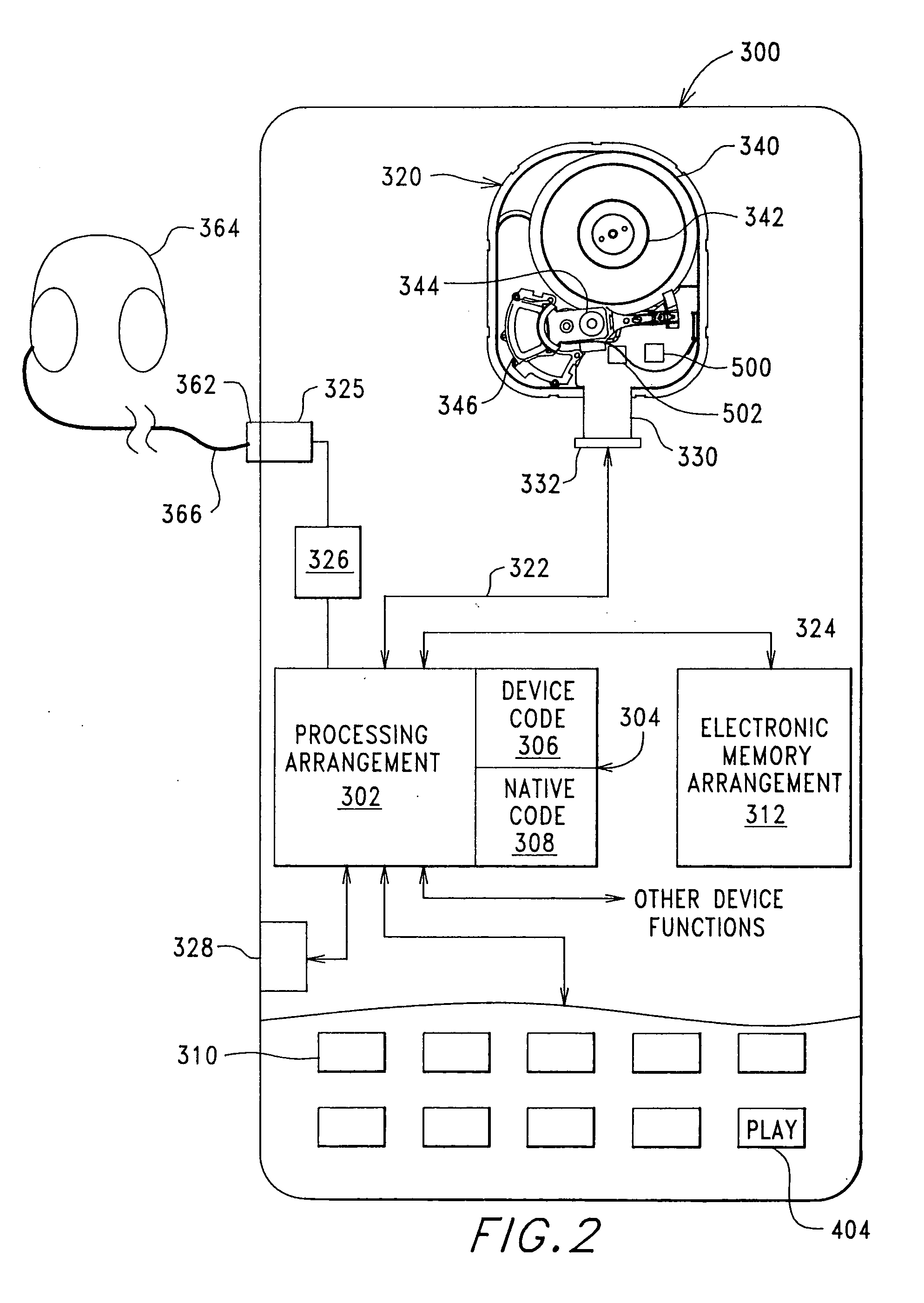
[0046] Returning now to the drawings, wherein like components are indicated by like reference numbers throughout the various figures, attention is immediately directed to FIG. 2, which illustrates an electronic device, generally indicated by the reference number 300, manufactured in accordance with the present invention. It is to be understood that device 300 is intended to be representative of any number of digitally implemented device types including, but not limited to wireless telephones, Internet appliances, personal digital assistants, music players, multi-function pagers, multimedia devices or any other device adaptable to use permanently installed digital storage of a size that is typically provided using electromechanical, rather than electronic storage. Moreover, the present invention facilitates the inclusion of additional functionality in devices traditionally having more limited, dedicated functionality. For example, a wireless phone may be provided including such featu...


PUM

PropertyMeasurementUnit
time periodsaaaaaaaaaa
timeaaaaaaaaaa
spin-up timeaaaaaaaaaa

Abstract

A digital Storage Element is described. A device is configured including a Storage Element for access by a user responsive to a native control code. A processing arrangement executes a control program for controlling the overall device and executing at least a portion of the native control code as part of the control program for interfacing with the Storage Element. A programming arrangement is provided separate from the device for customizing a read channel within the Storage Element. Command, user interaction and data transfer execution are discussed for mitigation of potential mechanical shock effects. Status indications relating to the Storage Element are provided including head position and mechanical shock. Calibration, test and operational monitoring procedures, for using head position status, are described. Failure configuration monitoring is provided in tracking overall performance and design considerations.

Description

[0001] The present application is a divisional application of co-pending U.S. patent application Ser. No. 09 / 952,998, filed on Sep. 14, 2001, which is incorporated herein by reference in its entirety.BACKGROUND OF THE INVENTION [0002] The present invention is related generally to a digital device architecture and, more particularly, to a digital system configuration and associated method for devices including an electromechanical data Storage Element. The invention is particularly well-suited for use in a portable device. [0003] One need only briefly survey virtually any public area in modern society in order to gain an appreciation for the popularity of electronic devices. Such devices include, but are not limited to cellular phones, music players, portable computers, personal digital assistants, pagers, digital cameras, digital camcorders, personal gaming devices and e-books. Continuous improvement has been seen in the capabilities present in these devices attributable, at least i...

Claims


Application Information

Patent Timeline
Patent Type & Authority Applications(United States)
IPC IPC(8): G06F1/16G06F3/06G06F13/12G06F13/14G06F13/16G06F13/38G11B5/54G11B15/18G11B17/00G11B19/02G11B19/04G11B20/10G11B21/02G11B21/08G11B21/12G11B21/22G11B27/36
CPCG06F3/0605G06F3/0625G06F3/0634G06F3/0653G11B5/4853G11B19/042G11B19/044G06F12/00Y02B60/1246G06F3/0674Y02D10/00G11B20/10G06F3/0659G06F3/0685
Inventor BRUNER, CURTIS H.FLETCHER, JOHN F.FLETCHER, FRIDA E. R.
Owner CORNICE
Why Eureka
Try Eureka