Signal processor
- Summary
- Abstract
- Description
- Claims
- Application Information
AI Technical Summary
Problems solved by technology
Method used
Image

Examples
embodiment 1
[0047] A first embodiment will now be discussed with reference to the figures.
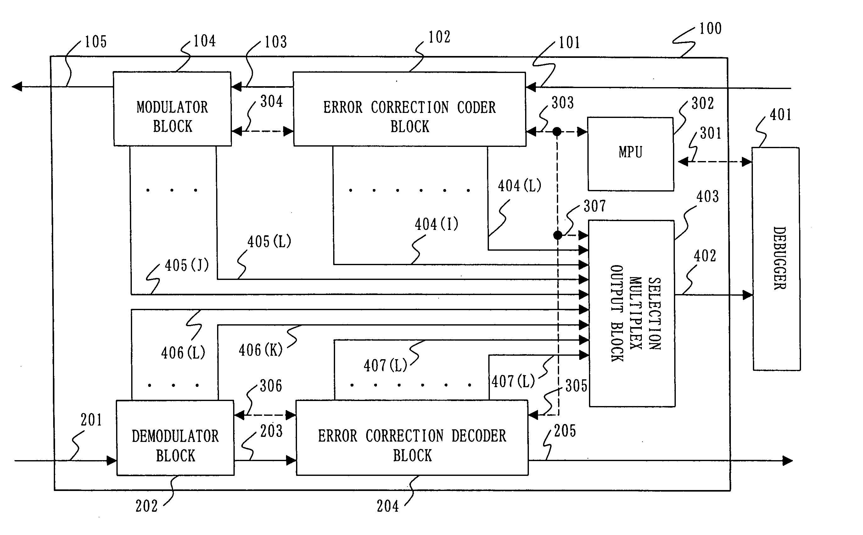
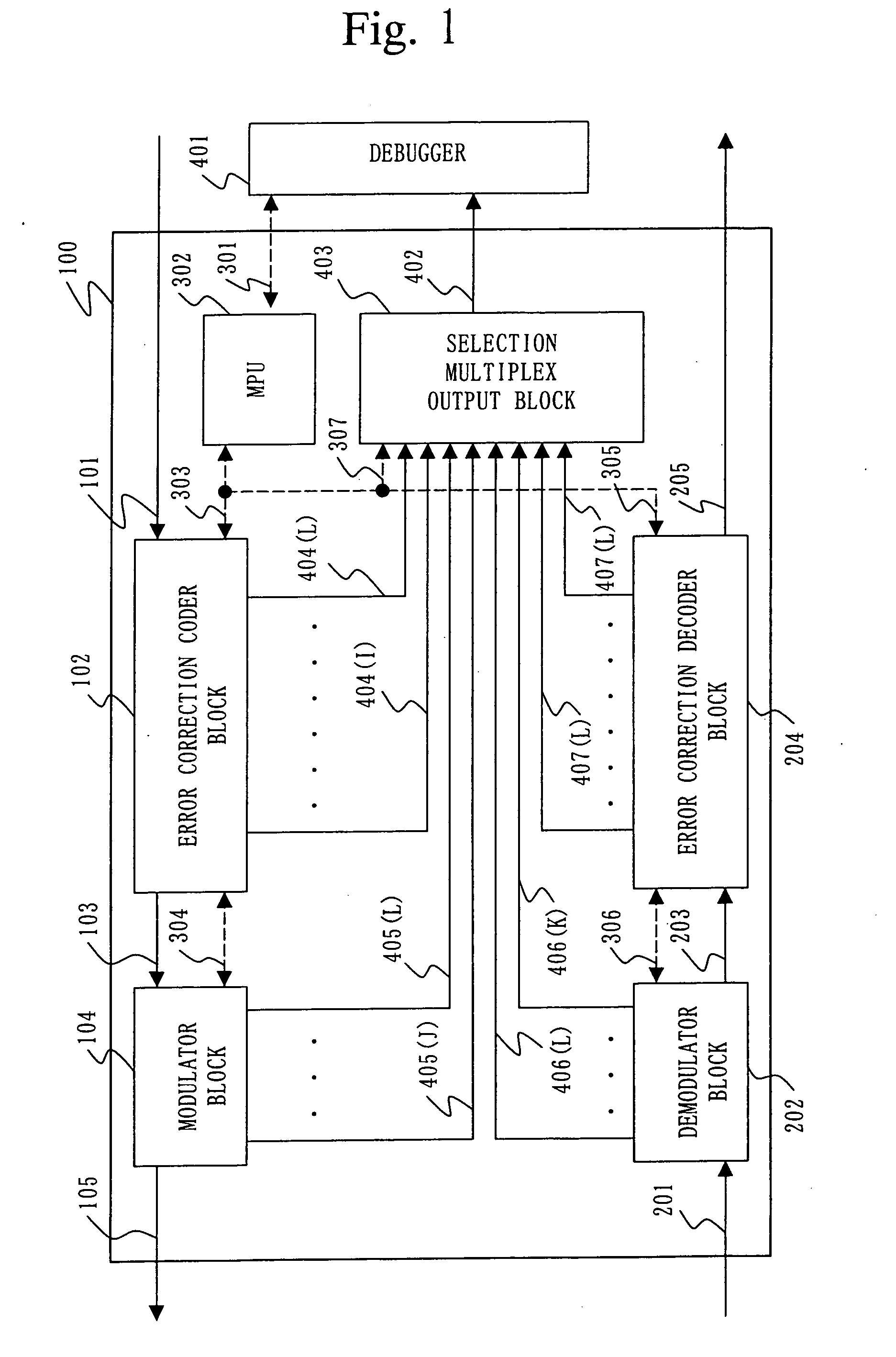
[0048]FIG. 1 is a block diagram of the configuration of a signal processor for a mobile communication system according to the first embodiment.
[0049] A reference numeral 100 denotes a signal processor for a mobile communication system. The signal processor 1000 is configured with a transmitter block and a receiver block.
[0050] The transmitter block has an error correction coder block 102 and a modulator block 104.
[0051] The error correction coder block 102 performs error correction coding, which is the signal processing that allows correcting an error bit produced in wireless transmission, for transmission data 101 for coding as the input data. The error correction coder block 102 outputs a coded data series 103. Error bit correction is necessary for improving line quality in wireless transmission.
[0052] The modulator block 104 modulates the coded data series 103 as the input data so as to convert the...
embodiment 2
[0075] A second embodiment will now be discussed with reference to the figures.
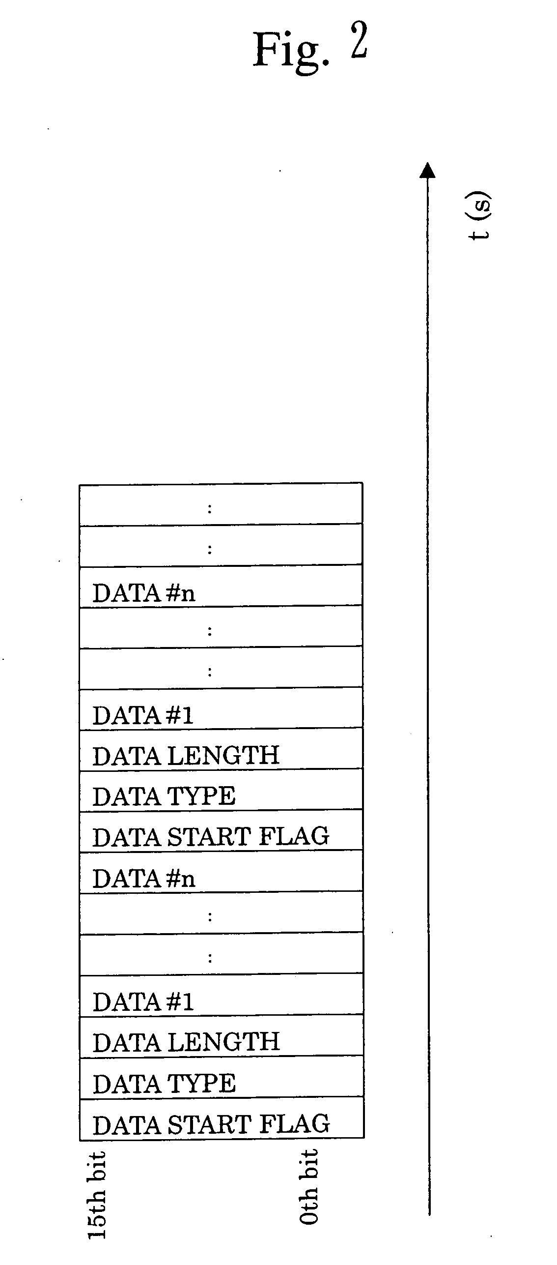
[0076]FIG. 4 is a diagram showing an example of the state of output in the case where a single piece of debug information including input data and / or output data is output from an arbitrary function block, when the debug information is added with time information. The time information is added to the debug information in the arbitrary function block.
[0077]FIG. 5 is a diagram showing an example of the state of multiplex output in the case where multiple pieces of debug information are output from one or more arbitrary function blocks, when the debug information is added with time information. This addition is performed in the arbitrary function blocks as well.
[0078] With the examples of FIG. 4 and FIG. 5, the debug information is assumed 16 bits. The debug information, as shown in the figures, includes a data start flag and a data length. The data start flag indicates a delimiter for the debug informati...
embodiment 3
[0083] A third embodiment of the present invention will now be discussed with reference to the figures. With the third embodiment, a description will be given of the case where a signal processor having the functions discussed in the first or second embodiment is combined with the debugger 401 of FIG. 1. Combining with the debugger 401 has the effect that a failure factor can be automatically specified.
[0084] The debugger of FIG. 1 has the function of instructing the MPU 302 to output the debug information to an arbitrary function block via the input / output signal line 301. The MPU 302, based on this instruction, controls the selection multiplex output block 403 via the input / output signal line 307. Also, the debugger has the function of retrieving debug information that is outputted as a result of the control via the selection multiplex output signal line 402.
[0085]FIG. 6 is a diagram illustrating an automation algorithm using a debugger for specifying a failure factor. More part...
PUM
 Abstract
Description
Claims
Application Information
 - R&D Engineer
- R&D Manager
- IP Professional
- Industry Leading Data Capabilities
- Powerful AI technology
- Patent DNA Extraction
Browse by: Latest US Patents, China's latest patents, Technical Efficacy Thesaurus, Application Domain, Technology Topic.
© 2024 PatSnap. All rights reserved.Legal|Privacy policy|Modern Slavery Act Transparency Statement|Sitemap