
Turntable with turning guide

Inactive Publication Date: 2005-09-08
KRAYER WILLIAM L
View PDF37 Cites 4 Cited by
  • Summary
  • Abstract
  • Description
  • Claims
  • Application Information

AI Technical Summary

Benefits of technology

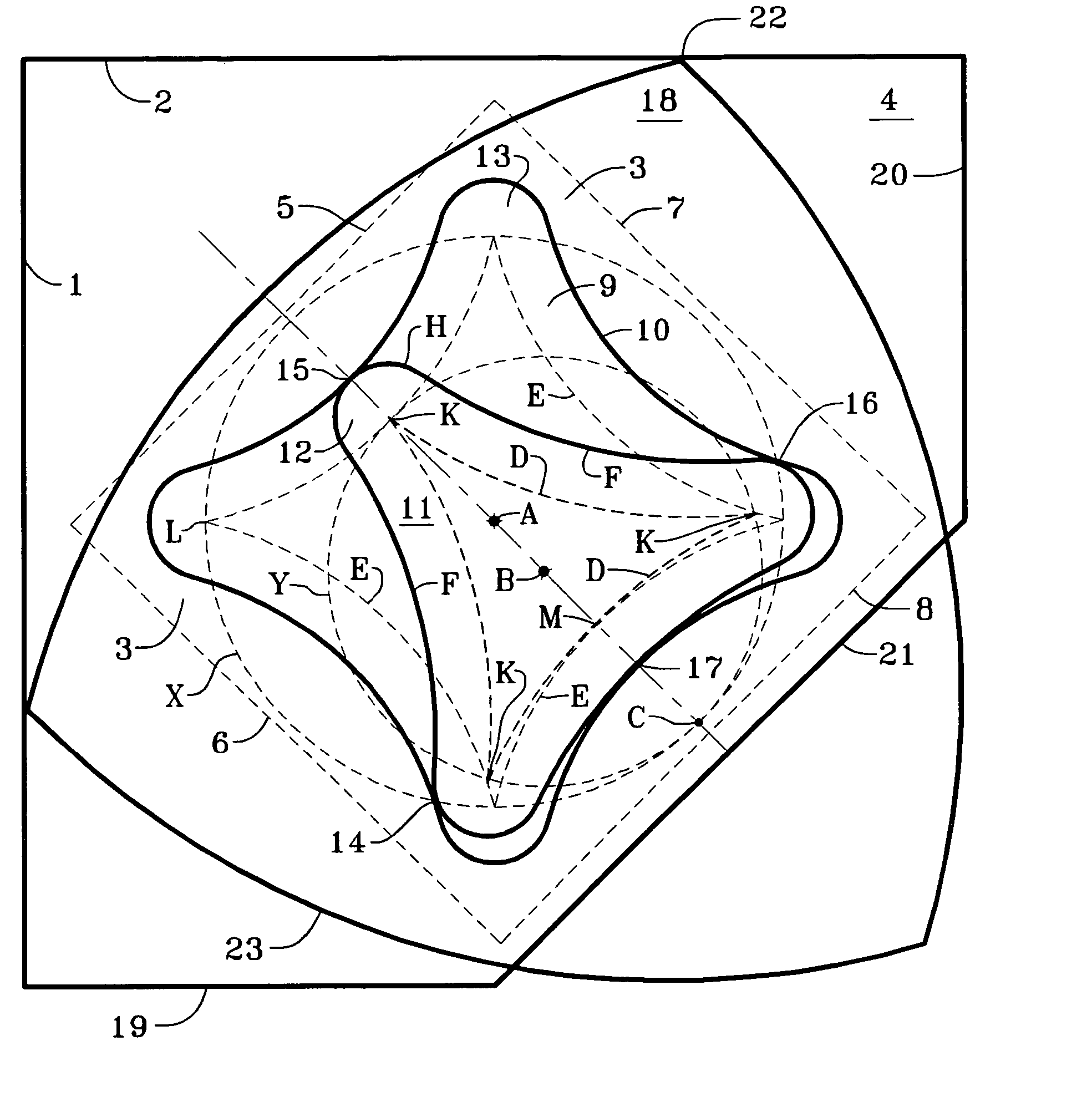
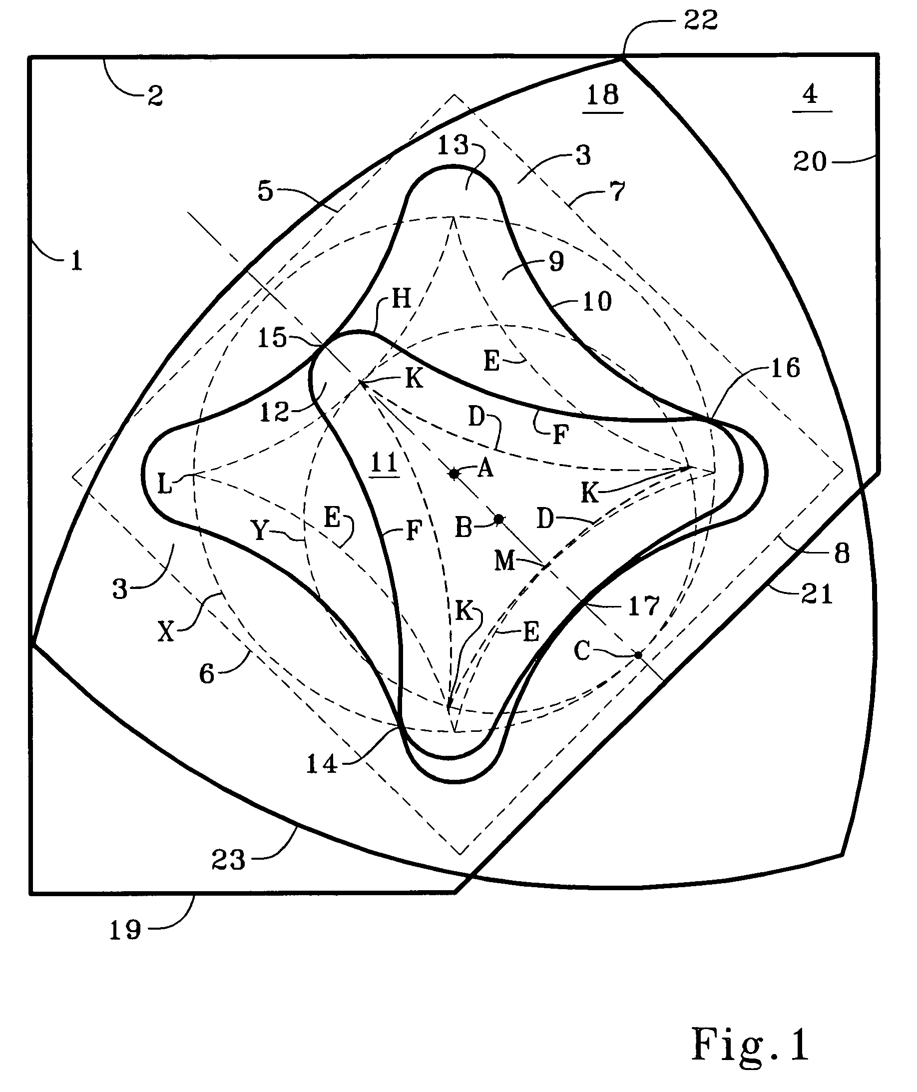
[0015] In another aspect, my invention utilizes a 4:3 hypocycloid rotation, and in particular the path followed by a point on the smaller circle as it rotates within the larger circle. Such a point will describe a concave square (see dotted lines E in FIG. 1). My invention includes the use of a rotor guide having a profile determined by expanding such a point path preferably by a distance of at least one-half the distance between the centers of the two circles. The expansion may be considerably larger, but I prefer between about 0.75 and 2 times the distance between the centers of the two circles. More preferably, the expansion dimension g will be between about 0.2R and 0.45R. If the expansion is less than about 0.125R, the rotor may be subject to jamming in the rotor guide but nevertheless may be useful in some circumstances; if it is larger than 0.5R, the rotor guide may be too large for some applications.
[0016] The term “gerotor” may appear in the prior art to describe either a gear-type member which rotates within a ring or internal gear element (that is, the ring or internal gear element is an element having gear-like “teeth” directed inwardly on the inside of a ring), or the assembly of both the gear-type member and the ring or internal gear element taken together. The rotating gear-type member generally has one fewer teeth than the relatively stationary internal or ring gear. In either case, it is understood that the assembly is designed so that the rotating gear-type member is confined to a rotation path such that its center must revolve around the center of the internal or ring gear, even without a rigid connection between the centers. This is normally accomplished by dimensioning both members so that when one of the teeth of the rotating member is at the full depth of a recess in the ring member, there are two teeth on its opposite side that are in contact with teeth on the ring member, preventing it from disengaging.
[0017] In the present description and claims, “gerotor” is used in the first sense - that is, to refer to the gear-type member which rotates within the relatively stationary ring or internal gear element, always in contact with the ring gear element on generally opposite sides so that its motion can only result in the revolution of its center around the center of the ring gear element. The relatively stationary ring or internal gear element is the “gerotor guide.”“Gerotor bearing” in the present specification means a gerotor having a substantially planar surface which can act as a load-bearing surface on a “gerotor guide bearing” or forming a bearing interface with a substantially planar surface such as a countertop or a cabinet floor. A “bearing interface” herein is created when one substantially planar surfac

Problems solved by technology

The ball casters were noisy and their durability was suspect.

Method used


Image

  • Turntable with turning guide
  • Turntable with turning guide
  • Turntable with turning guide

Examples


Embodiment Construction

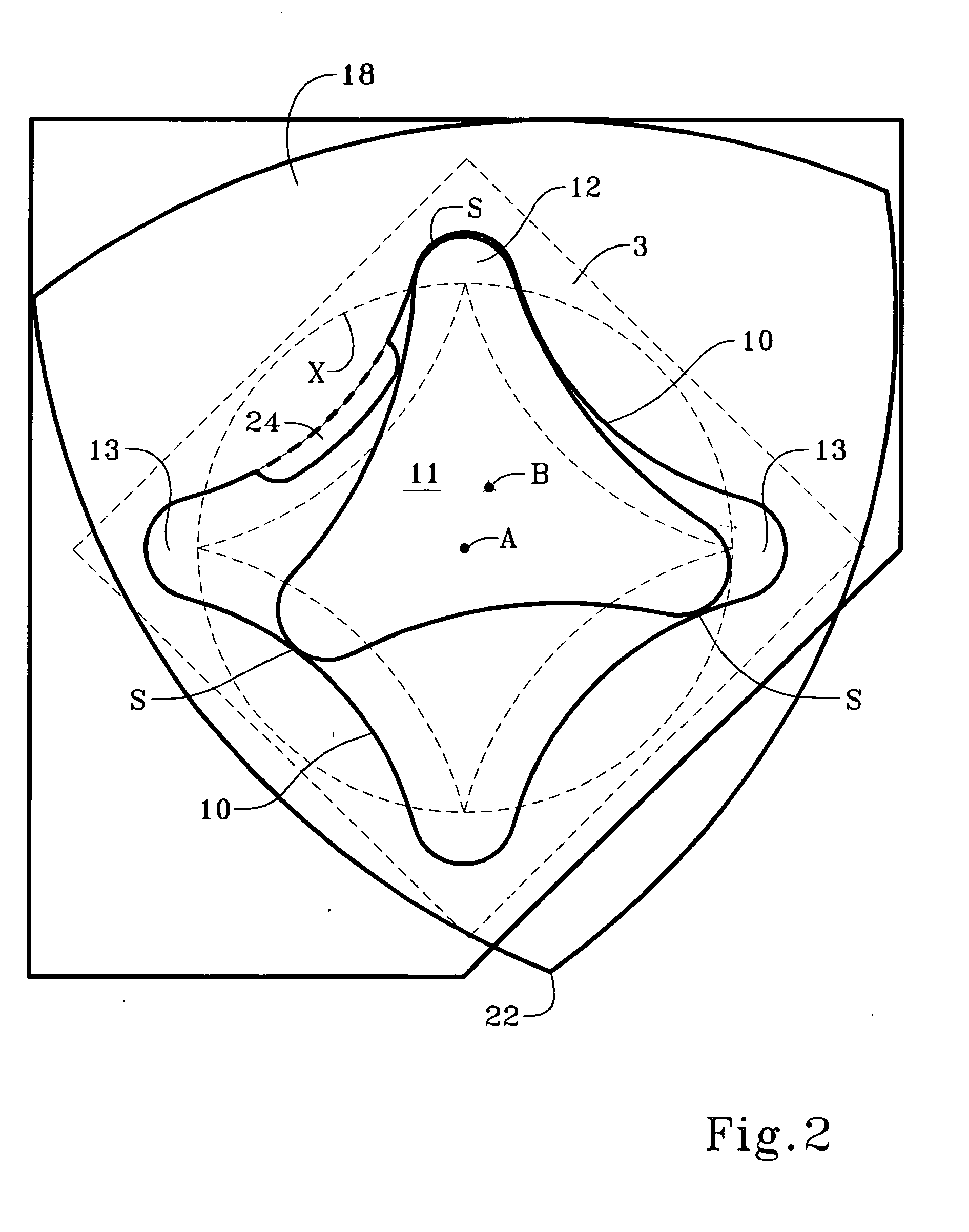
[0029] Referring to FIG. 1, an outline of a corner comprises substantially orthogonal walls 1 and 2, which may be either part of a building such as a kitchen wall, or integral to a cabinet. A gerotor guide 3 is placed on surface 4 of the corner. Surface 4 together with walls 1 and 2 could be a kitchen countertop, the floor or a shelf (a “level”) of a corner cabinet, or any other corner environment. Gerotor guide 3 may be a square, substantially flat element having a back 5, sides 6 and 7, a front 8, and center A. The principle feature of gerotor guide 3 is as a housing accommodating hollowed-out area 9. Hollowed-out area 9 is shaped to have a profile 10 preferably substantially as shown, which will be explained further below. Hollowed-out area 9 may be to a partial depth in gerotor guide 3 or entirely removed. If area 9 is hollowed out to a depth which leaves a surface in gerotor guide 3, the surface may be substantially planar and possibly low friction. If area 9 is entirely remove...


PUM


Abstract

A gerotor mechanism is used to guide the rotation of a turntable having a Reuleaux triangle shape. In one version, the mechanism includes a gerotor having three lobes, and the gerotor guide has a guide profile including four recesses for receiving the lobes of the gerotor. Rotation is governed by a 4:3 hypocycloid function. The profiles of the gerotor and the gerotor guide are expanded uniformly from an original hypocycloid pattern so that rotation of the turntable results in execution of the hypocycloid function while retaining the gerotor in controlled contact with the profile of the gerotor guide. A reciprocal of the hypocycloid function yields a “cloverleaf” gerotor. Substantially planar bearing surfaces may be used at the interface of (a) the turntable and the gerotor guide, (b) the gerotor and the gerotor guide, or (c) the gerotor and the underlying support surface. The gerotor guide and turntable may be part of a cabinet or built into a kitchen countertop.

Description

RELATED APPLICATIONS [0001] This is a continuation-in-part of application Ser. No. 10 / 791,596 filed Mar. 2, 2004, and also claims the full benefit of Provisional Applications 60 / 563,945 filed Apr. 22, 2004 and 60 / 578,580 filed Jun. 10,2004.TECHNICAL FIELD [0002] This invention relates to turntables, rotatable shelves, and lazy susans, particularly for corner cabinets and the back corners of kitchen countertops. The invention comprises an eccentric rotation and bearing system for a Reuleaux triangle shaped turntable. BACKGROUND OF THE INVENTION [0003] This invention is an improvement on Krayer U.S. Pat. No. 5,152,592, which discloses the use of a 4:3 hypocycloid rotation guide for rotating a shelf in the shape of a Reuleaux triangle. FIGS. 5A to 5H of the '592 patent illustrate that the rotation of a Reuleaux triangle-shaped shelf in a square area can be adapted to the floor or shelf of a corner cabinet such as a standard corner kitchen cabinet in a generally square shape. During the...

Claims


Application Information

Patent Timeline
IPC IPC(8): F01C1/02F01C1/063F04C18/00F16N13/20
CPCF16N13/20F01C1/10A47B49/006A47B96/025
Inventor KRAYER, WILLIAM L.
Owner KRAYER WILLIAM L
Learn More