Disposable/reusable flexible sensor

a flexible sensor and disposable technology, applied in the field of disposable devices, can solve problems such as economics of manufacture and ease of operation, and achieve the effect of facilitating the use of the device on a patien

Inactive Publication Date: 2005-09-08
MEASUREMENT SPEC
View PDF23 Cites 142 Cited by
  • Summary
  • Abstract
  • Description
  • Claims
  • Application Information

AI Technical Summary

Benefits of technology

[0012] The emitter and detector are connected together using wiring or other electrical connection means, and then to an outside measurement device through a wiring device. Preferably, the emitter and detector are both positioned adjacent the top of the sensor housing. Alternatively, both the detector and the emitter may actually extend out of the housing itself. To further enhance operation, the detector may have a conductive material on its rear side, such as copper, to prevent electromagnetic interference.
[0017] The present invention is further directed to a method for remanufacturing an otherwise disposable transillumination device, including the steps of (1) acquiring an otherwise disposable device, the device comprising a sealed sensor housing connected to a wiring device, and an attachment member for attaching the sensor housing to a patient; (2) removing the attachment member from the disposable device; (3) sanitizing and or sterilizing the sealed sensor housing and the wiring device; and (4) reassociating the sealed sensor housing with a new attachment member to, in turn, facilitate the use of the device on a patient.

Problems solved by technology

Although numerous devices are known in the art, there are still significant issues with economics of manufacture and ease of operation.

Method used


Image

  • Disposable/reusable flexible sensor
  • Disposable/reusable flexible sensor
  • Disposable/reusable flexible sensor

Examples


Embodiment Construction

[0025] While this invention is susceptible of embodiment in many different forms, there is shown in the drawings and will be described in detail, several specific embodiments with the understanding that the present disclosure is to be considered as an exemplification of the principles of the invention and is not intended to limit the invention to the embodiments illustrated.

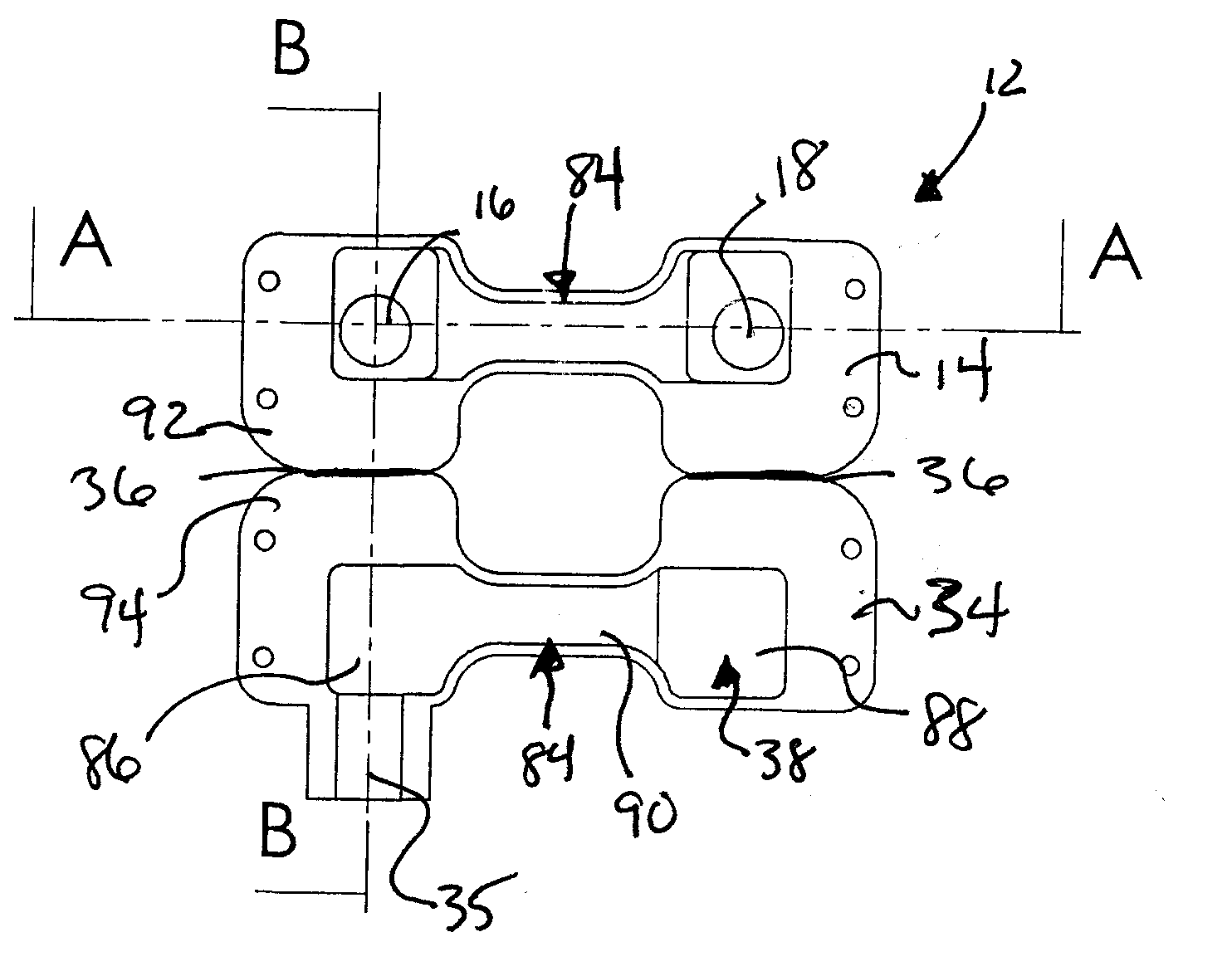
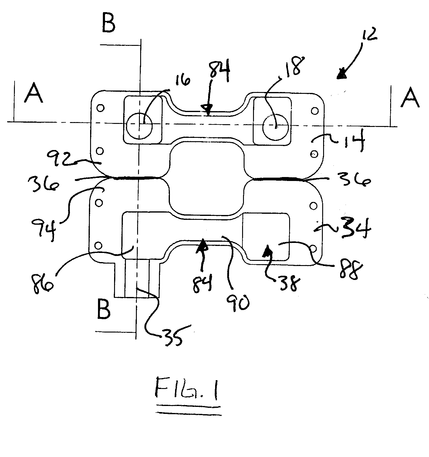
[0026] The present invention, as shown in FIG. 1, comprises an improved sensor housing for use in transillumination devices, such as SpO2 pulse oximetry sensors. Sensor housing 12 is shown in its pre-assembly condition as a single piece of molded, flexible material formed into top member 14 and bottom member 34, which are joined together at crease point 36. Top member 14 and bottom member 34 comprise a flexible, opaque material that is formed into substantial mirror image shapes, so that a user may fold top member 14 or bottom member 34 towards the other at crease point 34, forming enclosure 38 (shown best in FI...


PUM


Abstract

The present invention is directed to an improved pulse oximetry sensor device, in which the top and bottom portions of the sensor housing are affixed at a crease point, and are foldable towards each other to create an enclosure therebetween for retaining the optical elements of the device. The sensor housing may then be affixed to a patient by any number of methods, including using adhesive on a flexible strap, or by using a Velcro® strap on a flexible strap. Additionally discussed is a method of manufacturing such a device, and methods to reduce the manufacturing costs of an otherwise disposable device.

Description

BACKGROUND OF INVENTION [0001] 1. General Field of the Invention [0002] The present invention relates generally to devices for the non-invasive measurement of physiologic conditions, such as oxygen content of the blood through non-invasive pulse oximetry. Specifically, the present invention relates generally to devices for such measurement, and methods of manufacturing those devices. [0003] 2. Background of the Invention [0004] Noninvasive pulse oximetry is a well known technology, providing a wide range of devices in the art. Typically, such devices operate on the principles of light absorption by oxygenated and unoxygenated hemoglobin. By passing a known wavelength of light through the translucent tissues of a patient, and measuring the absorption of that light for a period of time, the oxygen content of the blood passing through that tissue can be measured. [0005] Although numerous devices are known in the art, there are still significant issues with economics of manufacture and ...

Claims


Application Information

Patent Timeline
Patent Type & Authority Applications(United States)
IPC IPC(8): A61B5/00
CPCA61B2562/12A61B5/14552
Inventor DIETIKER, THOMAS
Owner MEASUREMENT SPEC
Why Eureka
Try Eureka