Method and system for performing non-contact based determination of the position of an implement

a technology of position determination and implement, applied in the field of position determination systems, can solve the problems of reducing affecting the accuracy of position determination, so as to reduce the likelihood of damaging the antenna of the position determining system, reduce the likelihood of limiting the range of motion of the implement while it is being used, and facilitate installation

Active Publication Date: 2005-09-08
CATERPILLAR TRIMBLE CONTROL TECH
View PDF20 Cites 44 Cited by
  • Summary
  • Abstract
  • Description
  • Claims
  • Application Information

AI Technical Summary

Benefits of technology

[0010] Accordingly a need exists for a position determining system that can determine the location of an implement relative to a mobile machine to which it is coupled. While meeting the above stated need, it is advantageous for such a system to not restrict the range of motion of the implement. It is further advantageous to remove components of the position determining system from masts coupled with the implement to reduce the likelihood of damaging the components. Additionally, while meeting the above stated needs, it is advantageous that the position determining system may be installed on the mobile machine as an after market kit.
[0011] Embodiments of the present invention provide a position determining system that can determine the location of an implement relative to a mobile machine to which it is coupled. Additionally, embodiments of the present invention are less likely to restrict the range of motion of the implement while determining the location of the implement relative to a mobile machine to which it is coupled. Furthermore, embodiments of the present invention do not require the use of a mast-mounted system for determining the location of the implement relative to the mobile machine, thus reducing the likelihood of damaging components of the position determining system.
[0013] Embodiments of the present invention do not necessitate mounting antennas for a position determining system on masts coupled with the implement being used by the mobile machine in order to determine the geographic position of the working edge of the implement. This is advantageous because embodiments of the present invention reduce the likelihood of damaging the position determining system antennas and are less likely to restrict the range of motion of the implement while it is being used. Furthermore, embodiments of the present invention determine the position of the implement relative to the mobile machine without requiring measurement of the complete linkage geometry of each component disposed between the implement and the mobile machine. As a result, embodiments of the present invention can be more readily installed as an after market kit.

Problems solved by technology

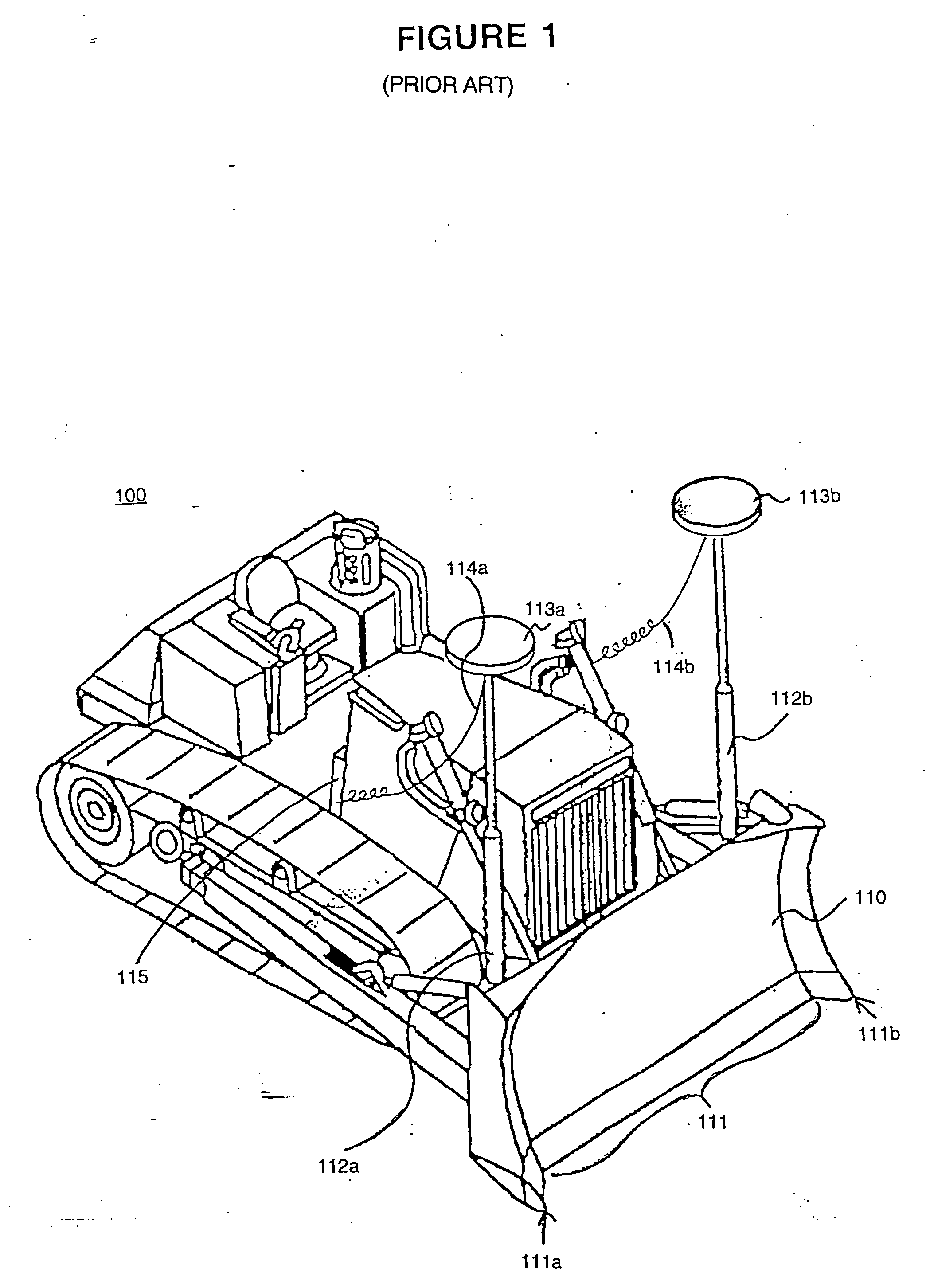
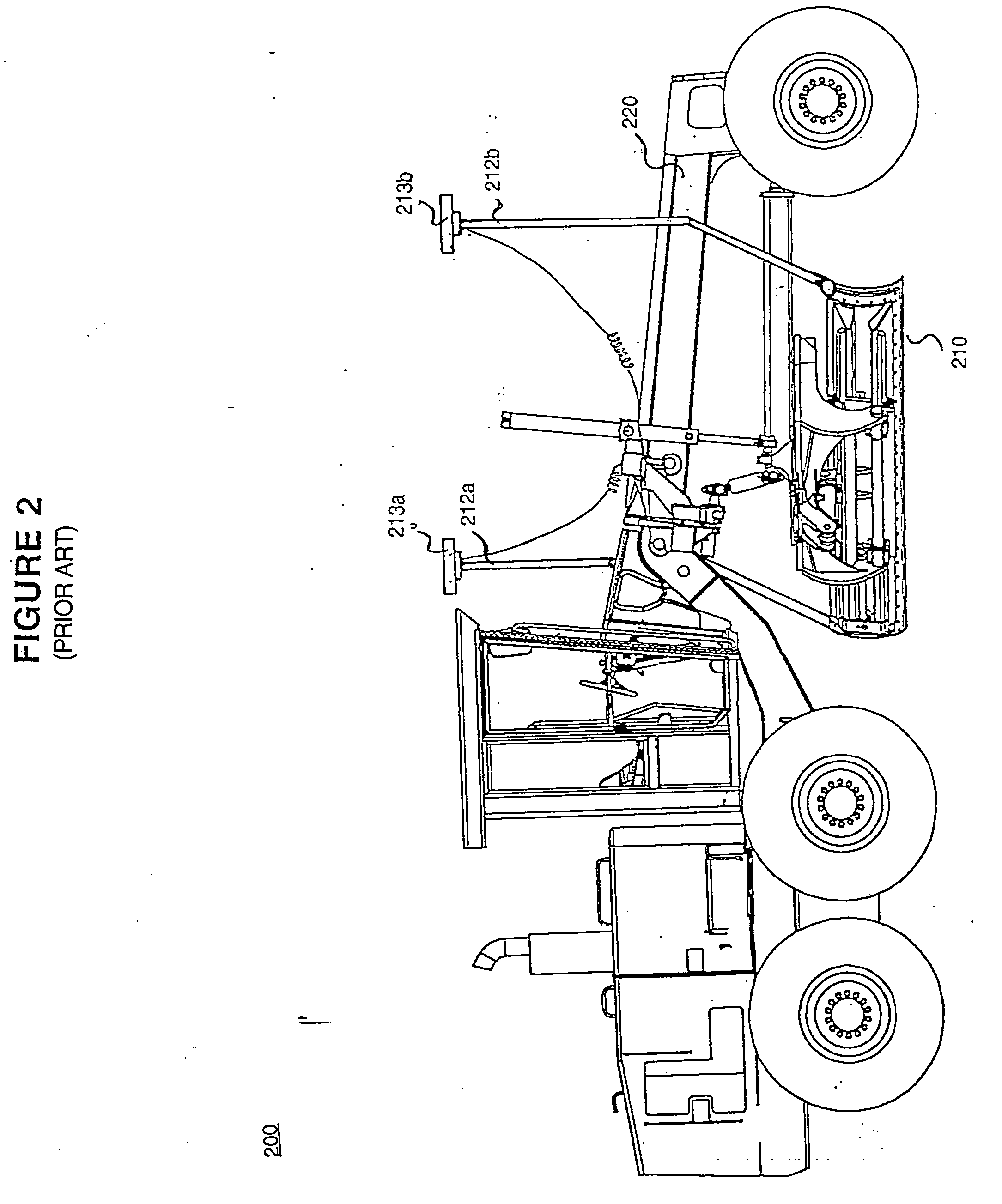
One disadvantage to the positioning system of FIG. 1 is the necessity of using masts 112a and 112b to support antennas 113a and 113b.
Another disadvantage of the positioning system of FIG. 1 is that the wires 114a and 114b coupling antennas 113a and 113b with a control unit 115 are exposed and susceptible to damage (e.g., from overhanging branches and / or brush).
Additionally, antennas 113a and 113b are exposed to a significant amount of vibration when blade 110 is being used, which can damage the antennas over time.
Using contact-based measurement systems to determine the position of the blade are disadvantageous in that they require some or all of: stepper motors, potentiometers, accelerometers, etc., to determine the position of the blade.
However, incorporating these components into the machine when it is built can be too expensive for some users and the after-market kits are still subject to the damage as described above.

Method used


Image

  • Method and system for performing non-contact based determination of the position of an implement
  • Method and system for performing non-contact based determination of the position of an implement
  • Method and system for performing non-contact based determination of the position of an implement

Examples


Embodiment Construction

[0022] Reference will now be made in detail to embodiments of the present invention, examples of which are illustrated in the accompanying drawings. While the present invention will be described in conjunction with the following embodiments, it will be understood that they are not intended to limit the present invention to these embodiments alone. On the contrary, the present invention is intended to cover alternatives, modifications, and equivalents which may be included within the spirit and scope of the present invention as defined by the appended claims. Furthermore, in the following detailed description of the present invention, numerous specific details are set forth in order to provide a thorough understanding of the present invention. However, embodiments of the present invention may be practiced without these specific details. In other instances, well-known methods, procedures, components, and circuits have not been described in detail so as not to unnecessarily obscure asp...


PUM


Abstract

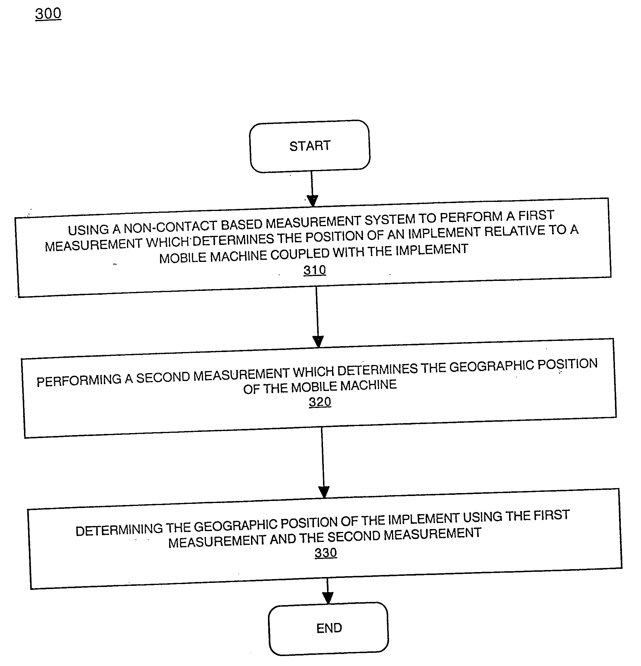
Embodiments of the present invention are directed to a method and system for performing non-contact based determination of the position of an implement. In one embodiment, a non-contact based measurement system is used to determine the relative position of an implement coupled with a mobile machine. The geographic position of the mobile machine is determined and the geographic position of said implement based upon the geographic position of the mobile machine and the position of the implement relative to the mobile machine.

Description

FIELD OF THE INVENTION [0001] Embodiments of the present invention are directed to position determination systems. More specifically, embodiments of the present invention are directed to a method and system for determining the position of an implement coupled with a mobile machine.RELATED APPLICATIONS [0002] The present Application claims priority to International Patent Application Number WO 99 / 28565 by Lars Ericsson, et al., filed on Nov. 27, 1998, entitled “Device and Method or Determining the Position of a Working Part” and assigned to the assignee of the present invention. BACKGROUND OF THE INVENTION [0003] Earth moving machines such as bulldozers, motor graders, scrapers, excavators, etc., are used to contour the ground for a variety of projects such as construction (e.g., roads, buildings, parks, and the like), mining, and agriculture. In order to achieve a pre-determined topography, it is important that soil is accurately removed from or added to selected areas. Therefore it...

Claims


Application Information

Patent Timeline
Patent Type & Authority Applications(United States)
IPC IPC(8): E02F3/84E02F9/20G01S19/04G01S19/10G01S19/44G01S19/46
CPCE02F3/842E02F3/847E02F9/264G06F17/00E02F9/2045G01C21/20E01C19/002E01C19/22E02F3/32E02F3/3414E02F3/7609E02F3/7636E02F9/261E02F9/265G01P15/121G01S19/10G05D2201/0202
Inventor TAYLOR, ARTHUR JAMESNICHOLS, MARKJACKSON, PHILIP
Owner CATERPILLAR TRIMBLE CONTROL TECH
Why Eureka
Try Eureka