Device on a spinning preparation machine, for example a tuft feeder, having a feed device

a technology of a preparation machine and a feed device, which is applied in the direction of carding machines, textiles and papermaking, fibre treatment, etc., can solve the problems of increasing the tension on the fibre material, inevitably affecting the speed and affecting the quality of the spinning preparation machin

Inactive Publication Date: 2005-09-15
TRUETZSCHLER GMBH & CO KG
View PDF7 Cites 31 Cited by
  • Summary
  • Abstract
  • Description
  • Claims
  • Application Information

AI Technical Summary

Benefits of technology

[0009] Because the appropriate belt speed is generated and set for every throughflow speed of the fibre material through the roller/tray system, the fibre material is prevented from being thrown upwards above the t

Problems solved by technology

In systems for the volumetric scanning of fibre streams, friction inevitably arises.
When there is a continuous stream of fibre material, such friction results in compaction of the fibre material in the direction of flow.
Particularly in the case of slow throughflow speeds, there is considerably more time available until the n

Method used


Image

  • Device on a spinning preparation machine, for example a tuft feeder, having a feed device
  • Device on a spinning preparation machine, for example a tuft feeder, having a feed device
  • Device on a spinning preparation machine, for example a tuft feeder, having a feed device

Examples


Embodiment Construction

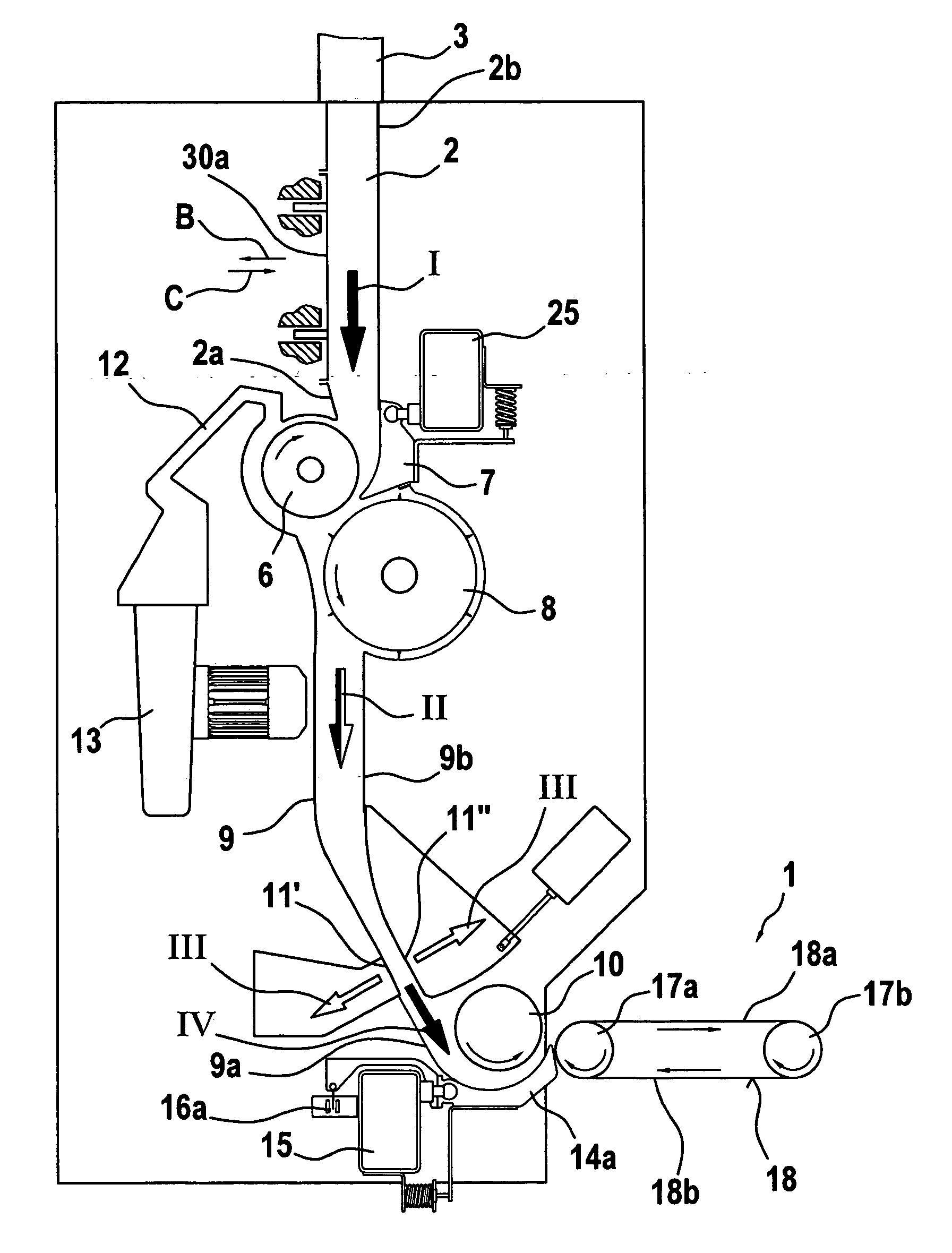
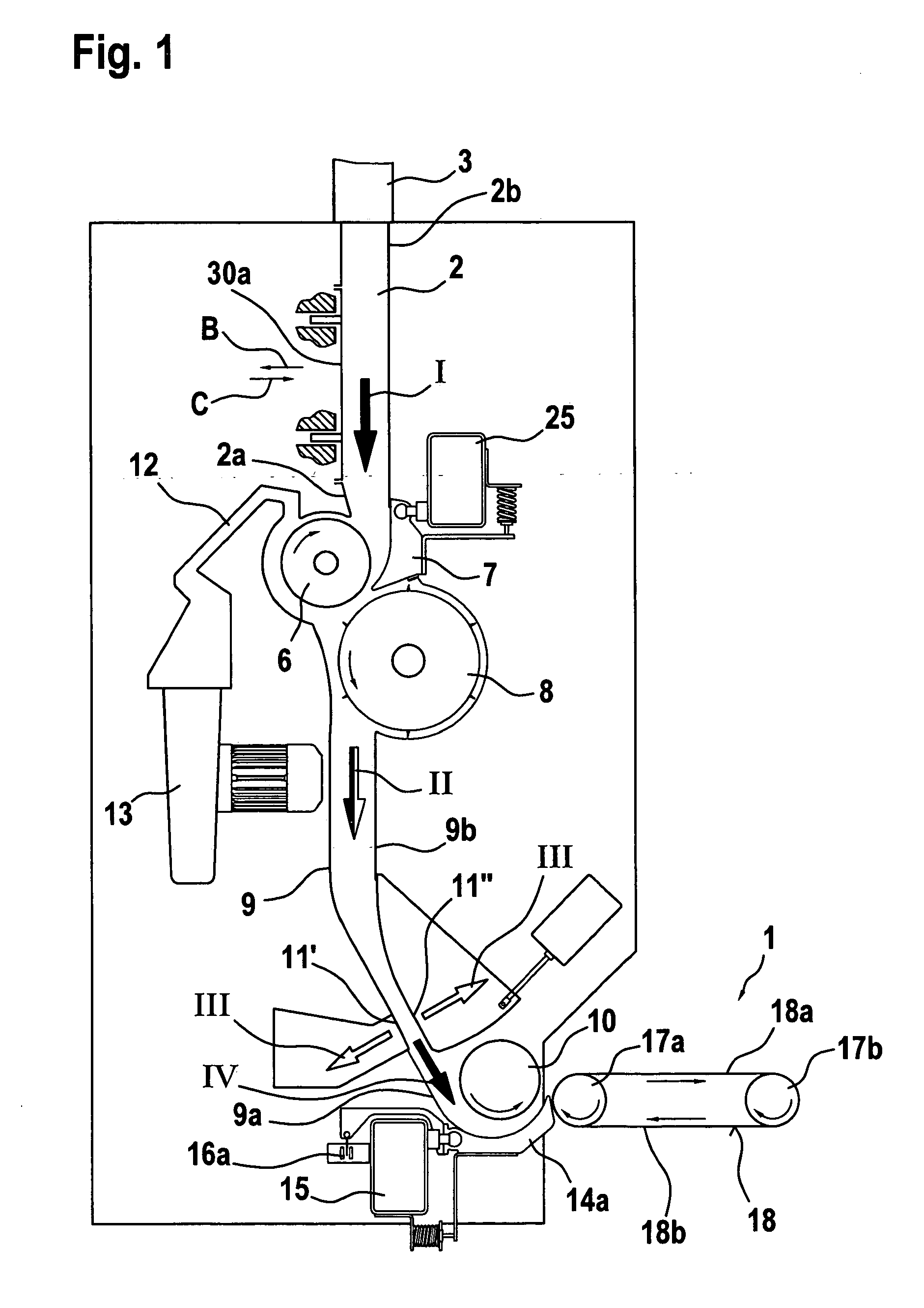
[0015] Referring to FIG. 1, upstream of a continuously circulating conveyor belt 1 there is provided a vertical reserve chute 2 which is charged from above with finely opened fibre material. Charging can be effected, for example, by means of a condenser through a supply and distributor line 3. In the upper region of the reserve chute 2 there are air outlet openings 4 through which the transport air, after being separated from the fibre flocks I, passes into an extractor device. The lower end of the reserve chute 2 is closed by an intake roller 6 which cooperates with an intake tray 7. By means of this slow-speed feed roller 6, the fibre material is supplied from the reserve chute 2 to a high-speed opener roller 8 that is located below the reserve chute and is covered with pins 8b or sawtooth wire, which opener roller 8 is associated over a portion of its circumference with a lower feed chute 9. The opener roller 8, which rotates in the direction of arrow 8a, transports the fibre mat...


PUM


Abstract

A device on a spinning preparation machine, for example a tuft feeder, having a feed device comprising at least one slow-speed feed roller and a counter-element, for example a feed tray, with which fibre material can be supplied to a downstream transport device, has a driven transport element, for example a conveyor belt. In order to provide improved delivery from the feed device, or improved takeover by the downstream transport device, and to allow troublefree operation, for the purpose of determining setting values for the optimum speed of the transport element, a function between the measured values of the feed roller speed and the measured values of the transport speed is so determined that the fibre material lies on the moving surface of the transport element.

Description

CROSS REFERENCE TO RELATED APPLICATION [0001] This application claims priority from German Patent Application No. 10 2004 012 236.9 dated Mar. 12, 2004, the entire disclosure of which is incorporated herein by reference. BACKGROUND OF THE INVENTION [0002] The invention relates to a device on a spinning preparation machine, for example a tuft feeder, having a feed device comprising at least one slow-speed feed roller and a counter-element, for example a feed tray, with which fibre material can be supplied to a downstream transport device having a driven transport element, for example a conveyor belt. [0003] In systems for the volumetric scanning of fibre streams, friction inevitably arises. When there is a continuous stream of fibre material, such friction results in compaction of the fibre material in the direction of flow. Once the fibre stream has emerged from the gap of the roller / tray system, the tension on the fibre material is relaxed and the fibre material assumes a higher ex...

Claims


Application Information

Patent Timeline
IPC IPC(8): D01G9/16D01G15/40D01G9/18D01G23/00D01G23/02D01G23/04D01G23/06D01G25/00
CPCD01G15/40D01G23/04D01G23/02D01G9/16D01G23/00
Inventor RUBENACH, BERNHARD
Owner TRUETZSCHLER GMBH & CO KG
Why Eureka
Try Eureka