Handlebar clamp

a technology for clamping handlebars and handlebars, which is applied in the direction of steering devices, cycle equipments, mechanical apparatus, etc., can solve the problems of determining the fretting amount between the handlebar and the clamp, and achieve the effects of reducing compressive stress, preventing deformation and tensile stress, and preventing any fretting damag

Inactive Publication Date: 2005-09-15
RENTHAL
View PDF16 Cites 10 Cited by
  • Summary
  • Abstract
  • Description
  • Claims
  • Application Information

AI Technical Summary

Benefits of technology

[0016] The provision of a protective component overlying this location on the handlebar previously most vulnerable to fatigue failure, ie adjacent the end of the clamp, prevents any fretting damage at this location, prevents deformation and tensile stress and also substantially reduces compressive stress at this location. Only the in service stress caused by handlebar deflection in use remains.

Problems solved by technology

In use, there is also a certain amount of fretting between the handlebar and the clamp caused by the deflection of the handlebar under load.
All of these factors, namely the compressive stress of clamping, the tensile stress caused by surface deformation, fretting damage and in use deflection under load, contribute to any fatigue failure of a handlebar.

Method used


Image

  • Handlebar clamp
  • Handlebar clamp
  • Handlebar clamp

Examples


Embodiment Construction

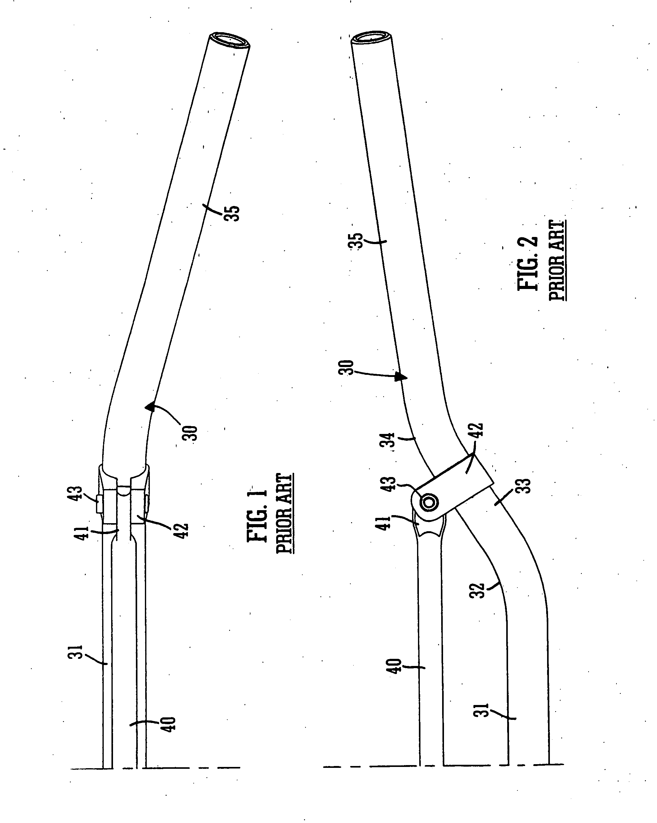
[0029]FIGS. 1 and 2 show the configuration of a conventional 7 / 8 inch (22.23 mm) diameter motorcycle handlebar 30. The other half is, of course, symmetrical. A central section 31 leads at each end, via a proximal bend 32 to an intermediate or bent section 33. This leads, via a respective distal bend 34 to a respective end section 35, which is also bent out of the plane of the central and intermediate sections 31, 33 as is apparent from FIG. 1. The handlebar 30 is typically of tubular form, i.e. hollow, and of an aluminium alloy, although steel handlebars are also known. A cross brace 40, which is a simple rod of the same metal or alloy formed with flattened straps or ears 41 at each end is fitted between the intermediate or bent sections 33 by means of respective cross brace clamps 42. Each cross brace clamp 42 surrounds the bar 30 and has opposed end margins which are secured. In the illustrated version they are secured by a bolt 43 which also extends through the end 41 of the cros...


PUM


Abstract

In respect of a clamp arrangement for the centre of a handlebar, which may comprise a pair of spaced clamps or a single clamp, or for securing a cross brace to a handlebar, the provision of a protective component, such as a nylon sleeve or other polymeric insert, between the or each clamp and the bar at the edge margin (or respective edge margins) of the clamp nearest the end of the bar greatly increases the fatigue life of the bar. The protective component is seated in a recess and only extends part way in from the edge of the clamp, so that there is still sufficient direct clamping between the material of the clamp or clamps and the bar to prevent any rotation of the bar.

Description

TECHNICAL FIELD OF THE INVENTION [0001] This invention concerns a clamp for a handlebar. It is particularly suitable for a motorcycle handlebar, but could also be applied to a handlebar for a bicycle, a jet ski, a scooter, a quad bike or any other vehicle. [0002] Handlebars for many such vehicles are typically of tubular form. Traditionally they were made of steel, but nowadays aluminium or an alloy thereof is the preferred material. The invention is applicable to a clamp for any handlebar, of any configuration, whether of metal, as is conventional, or of other material, such as carbon fibre. BACKGROUND OF THE INVENTION [0003] Handlebars are typically clamped at a central location, by a single mounting or a pair of spaced mounting means. In respect of motorcycle handlebars, each mounting usually comprises an upper and a lower clamp element formed with corresponding part-cylindrical clamping surfaces and fastened together, encircling and clamping a handlebar there between, by two or ...

Claims


Application Information

Patent Timeline
Patent Type & Authority Applications(United States)
IPC IPC(8): B62K21/12
CPCB62K21/12Y10T74/2078B62K21/18
Inventor RENSHAW, ANDREW CHARLES
Owner RENTHAL
Why Eureka
Try Eureka