
Clip on thermal welder

a welder and clip technology, applied in the field of clip on thermal welders, can solve the problems of essentially slow sealing rate, difficult or painful use of hand held sealers, and relatively fragile plastic tubing used in conjunction with blood collection

Active Publication Date: 2005-09-15
VANTE
View PDF16 Cites 5 Cited by
  • Summary
  • Abstract
  • Description
  • Claims
  • Application Information

AI Technical Summary

Benefits of technology

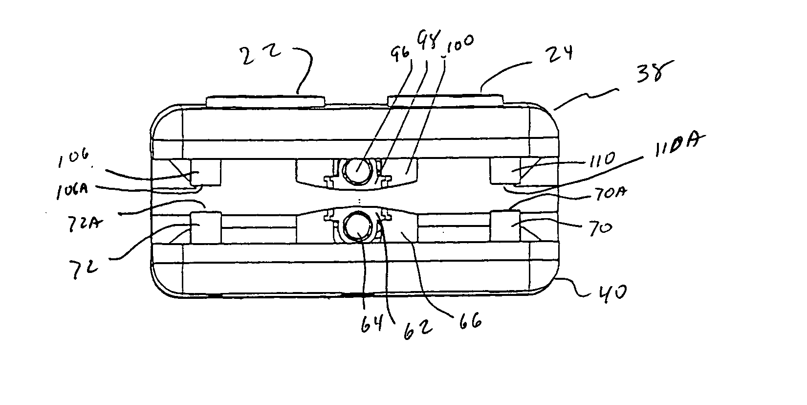
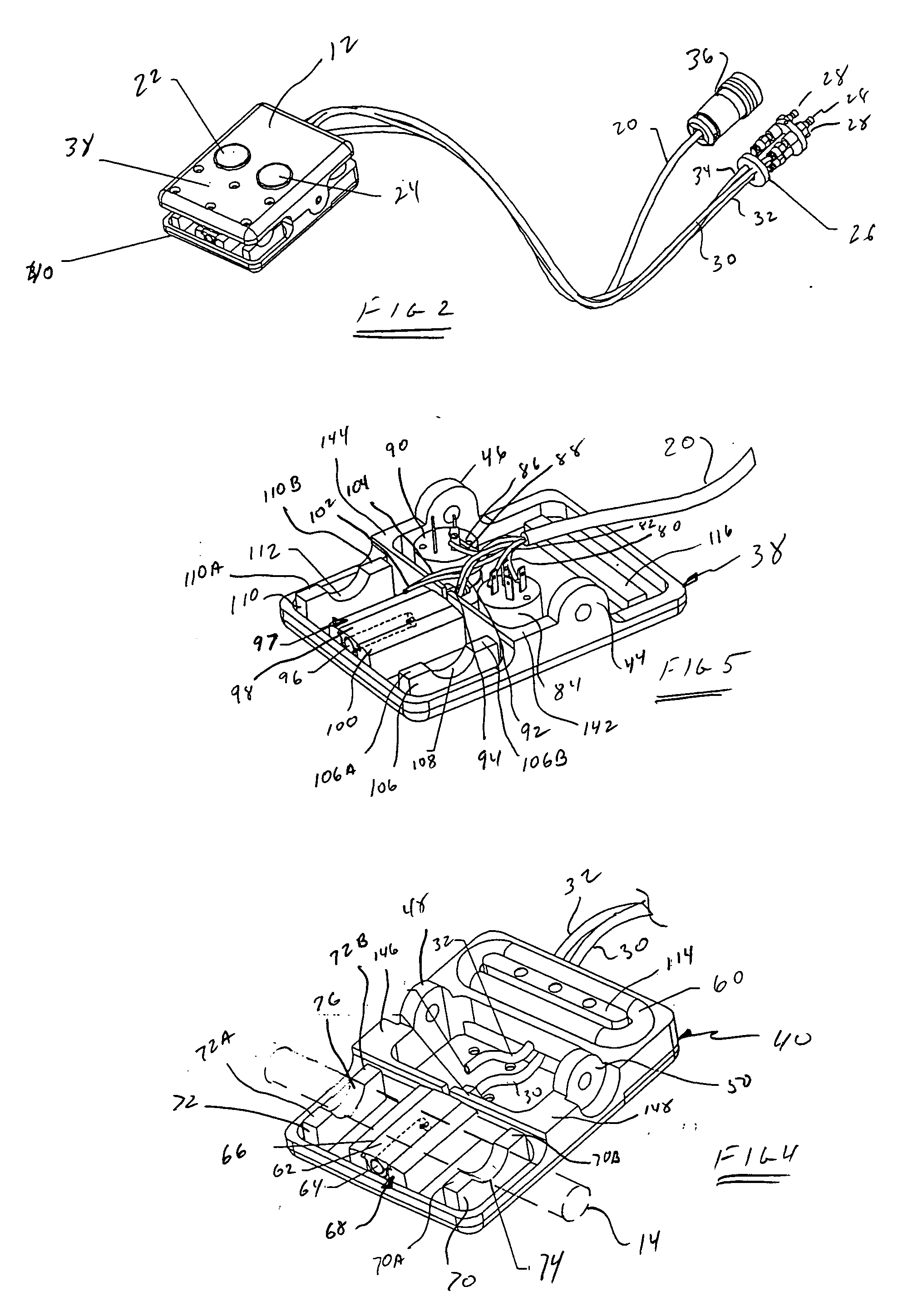
[0015] A clip on welder includes two pairs of opposed grippers defined by pivotally attached upper and lower frames for latching the welder to a length of tubing. By pushing a start button an operator will cause a bellows to inflate in response to air flow from a source of compressed air to force the frames to pivot relative to one another and bring two pairs of grippers into latching engagement with the tubing. At least a jaw of a pair of jaws disposed intermediate the two pairs of grippers thereafter heats the tubing compressed and lodged therebetween to form a weld across the tubing. A source of electrical signals actuated by the operator pushing the start button provides the power to heat the jaws which heat the tubing intermediate the pair of jaws.
[0019] Still another object of the present invention is to provide a tubing welder for forming a weld in tubing which welder may be attached to and removed from a length of the tubing at the convenience of an operator and without requiring attendance by the operator during formation of the weld.
[0020] Yet another object of the present invention is to provide a clip on tubing welder that requires minimal instruction on the operation of the welder.

Problems solved by technology

Plastic tubing, particularly of the type used in conjunction with the collection of blood, is relatively fragile and is easily burst when heated to a temperature close to its melting point.
For those persons whose hands are not strong or who suffer pain when they attempt to grip an article with their hands, a hand held sealer is difficult or painful to use.
Consequently, the rate of production of seals is essentially slower than optimum.

Method used


Image

  • Clip on thermal welder
  • Clip on thermal welder
  • Clip on thermal welder

Examples


Embodiment Construction

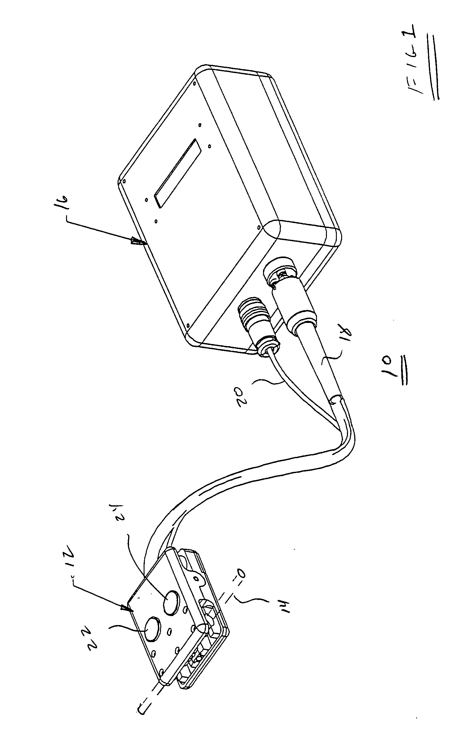
[0041] Referring to FIG. 1, there is shown a tubing welder assembly 10 for performing a seal across a heat weldable length of tubing. The assembly includes a clip on welder 12 engaging a representative length of tubing 14 engaged thereby, as illustrated. A support housing 16 contains a source of a gas, such as air, under pressure (not shown) and a source of electrical signals (not shown). The gas under pressure is conveyed through a plurality of pneumatic conduits enveloped within a sleeve 18 to welder 12. A plurality of electrical signals are conveyed from within housing 16 through a cable 20 to the welder. After the welder has been brought into engagement with tubing 14, as illustrated, a start button 22 is depressed. On actuation of the start button, the tubing will be gripped by the welder to support the welder and permit unattended operation of the welder during formation of the weld across the tubing to form a seal. On completion of the weld, the element(s) providing the requi...


PUM

PropertyMeasurementUnit
Temperatureaaaaaaaaaa
Lengthaaaaaaaaaa
Thicknessaaaaaaaaaa

Abstract

A clip on welder includes two pairs of opposed grippers defined by pivotally attached upper and lower frames for latching the welder to heat weldable material, such as a length of tubing, upon actuation of a start button by an operator; thereafter, the welder operates unattended. At least a jaw of a pair of jaws disposed intermediate the two pairs of grippers heats the material compressed and lodged therebetween to form a weld in or across the material. A source of gas, such as air, under pressure selectively connected to a bellows provides the power to pivot the upper and lower frames into gripping engagement with the material. A source of electrical signals provides the power to heat the material intermediate the pair of jaws. One or more thermocouples senses the heat of the jaws and generates signals used to control the application of power and to control cooling. After completion of the weld, cooling air is directed to the jaws until the thermocouple(s) signal(s) indicates a sufficiently low temperature. Release of the welder from the material is in response to actuation of a stop button by the operator.

Description

BACKGROUND OF THE INVENTION [0001] 1. Technical Field of the Invention [0002] The present invention relates to tubing welders and, more particularly, to clip on unattended welders for forming a seal in a length of tubing to seal the tubing. [0003] 2. Description of Related Art [0004] It is well known that plastic materials may be welded to one another by the application of heat. Many prior art devices developed for this purpose are essentially immobile units particularly adapted for mass production requirements in a manufacturing facility. [0005] As suggested above, plastic materials may be welded to one another by application of heat. Numerous devices have been developed for this purpose of which the following descriptions are representative. U.S. Pat. No. 2,529,717 describes an RF energized heat sealer wherein one electrode of a pair of electrodes is removable to accommodate placement of the material to be sealed between the electrodes; a constant RF energy level is applied for a ...

Claims


Application Information

Patent Timeline
CPCB29C65/04B29C66/961B29C65/14B29C65/18B29C65/305B29C66/1122B29C66/4312B29C66/81811B29C66/8242B29C66/83241B29C66/861B29C66/872B29C66/91231B29C66/9131B29C66/91421B29C66/91431B29C66/91641B29C66/91212B29C65/08B29C65/7841B29C66/81821B29C66/8221B29C66/8227B29C66/82421B29C66/8618B29C66/9672
Inventor JENSEN, JOSEPH C.
Owner VANTE
Learn More