
Air-to-air heat exchanger

a heat exchanger and air-to-air technology, applied in indirect heat exchangers, lighting and heating apparatus, spacing means, etc., can solve the problems of insufficient heat exchangers, disadvantageously large inherent thermal impedances, and insufficient resistan

Inactive Publication Date: 2005-09-15
THERMAL
View PDF18 Cites 20 Cited by
  • Summary
  • Abstract
  • Description
  • Claims
  • Application Information

AI Technical Summary

Problems solved by technology

A significant disadvantage in prior art heat-exchangers of this type is the inherent thermal impedance, i.e., resistance to thermal conduction through the thickness of the plate, associated with the materials used to form the heat-exchange plates.
These design requirements typically require a minimum material thickness (e.g., a material thickness that is some minimum percentage of the plate's width or length) that results in a disadvantageously large inherent thermal impedance.
Polymer materials typically exhibit significant dielectric and thermal insulating properties that preclude their use in heat-exchange plates, especially when they are required to provide structural integrity to the device.

Method used


Image

  • Air-to-air heat exchanger
  • Air-to-air heat exchanger
  • Air-to-air heat exchanger

Examples


Embodiment Construction

[0026] This description of preferred embodiments is intended to be read in connection with the accompanying drawings, which are to be considered part of the entire written description of this invention. The drawing figures are not necessarily to scale and certain features of the invention may be shown exaggerated in scale or in somewhat schematic form in the interest of clarity and conciseness. In the description, relative terms such as “horizontal,”“vertical,”“up,”“down,”“top” and “bottom” as well as derivatives thereof (e.g., “horizontally,”“downwardly,”“upwardly,” etc.) should be construed to refer to the orientation as then described or as shown in the drawing figure under discussion. These relative terms are for convenience of description and normally are not intended to require a particular orientation. Terms including “inwardly” versus “outwardly,”“longitudinal” versus “lateral” and the like are to be interpreted relative to one another or relative to an axis of elongation, o...


PUM


Abstract

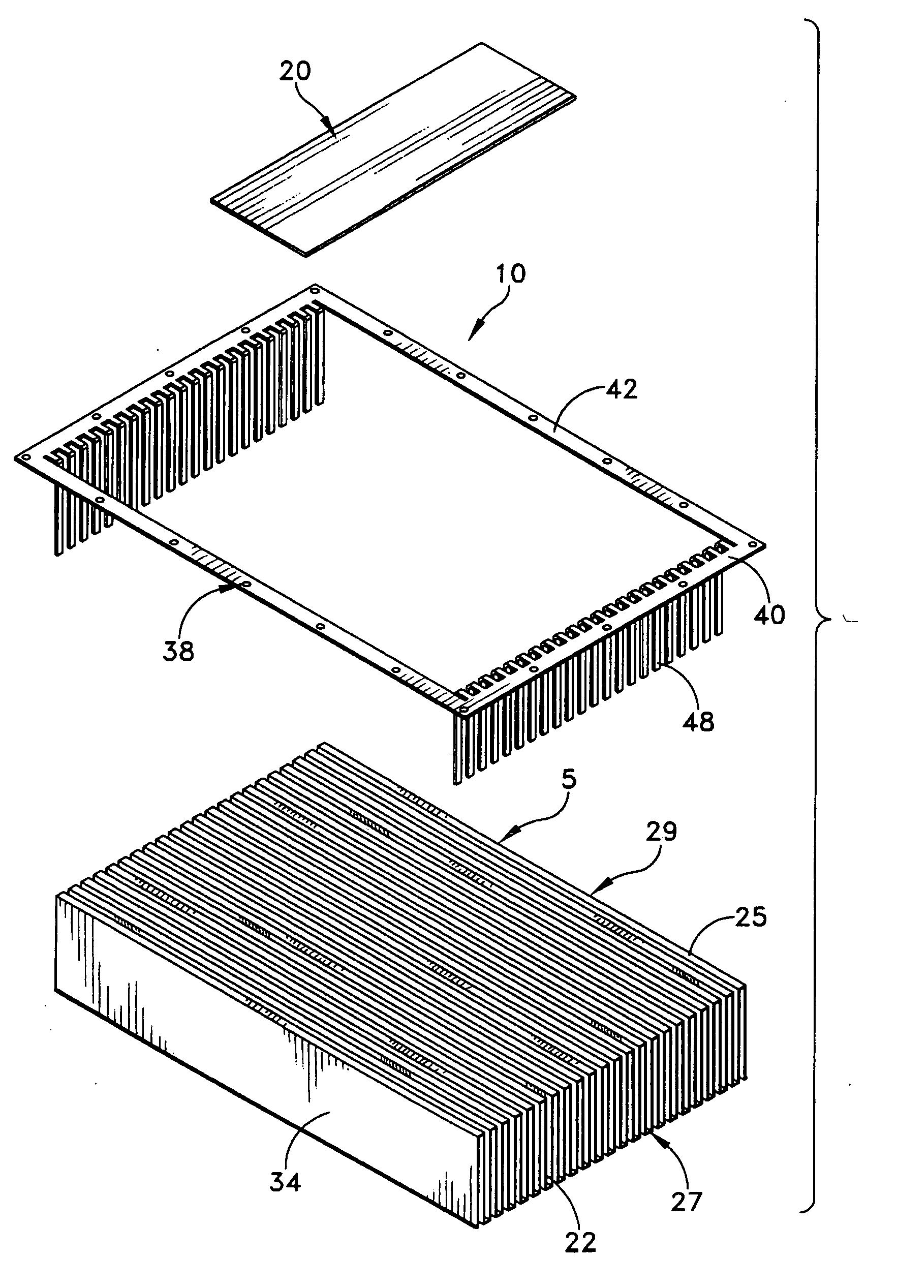
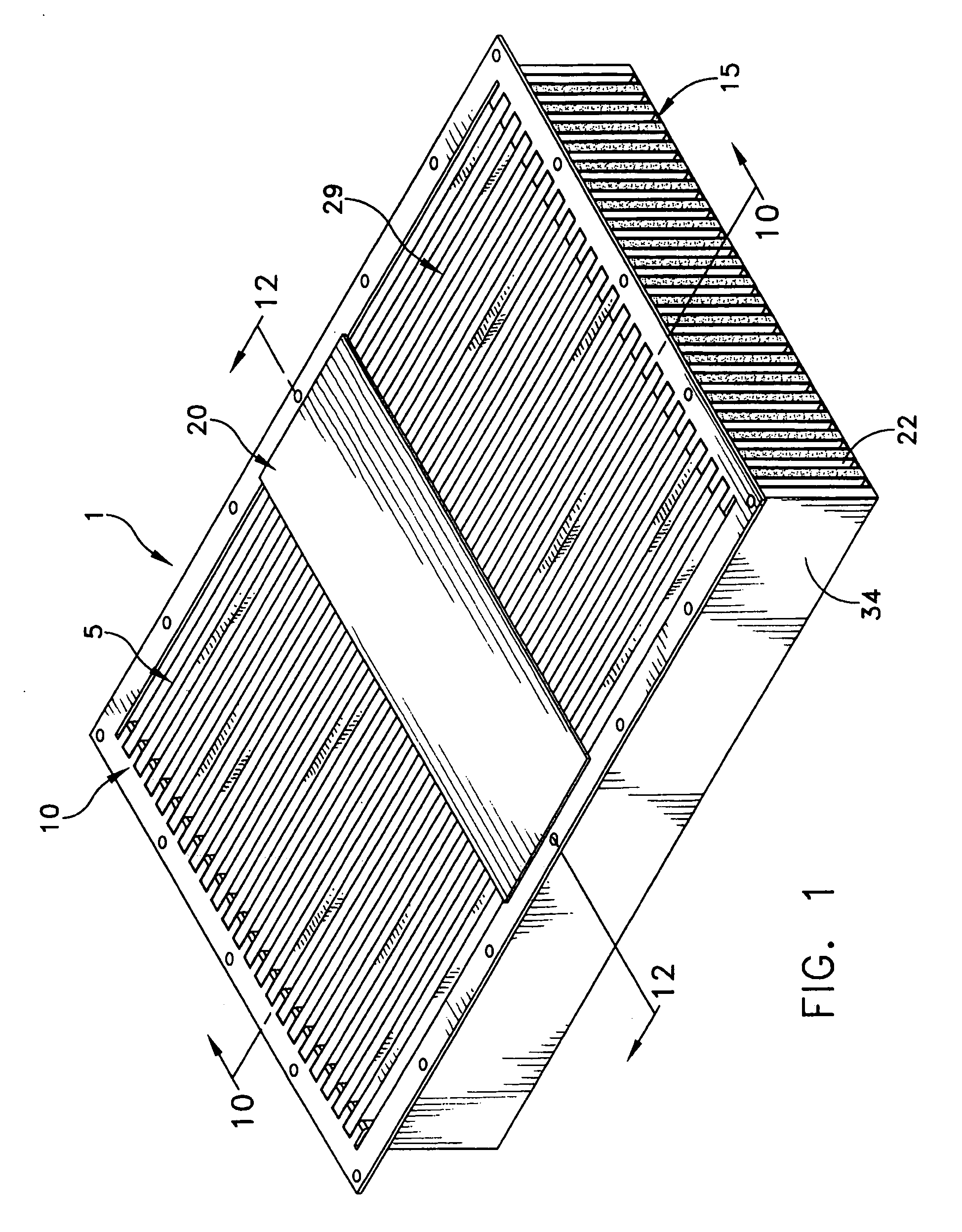
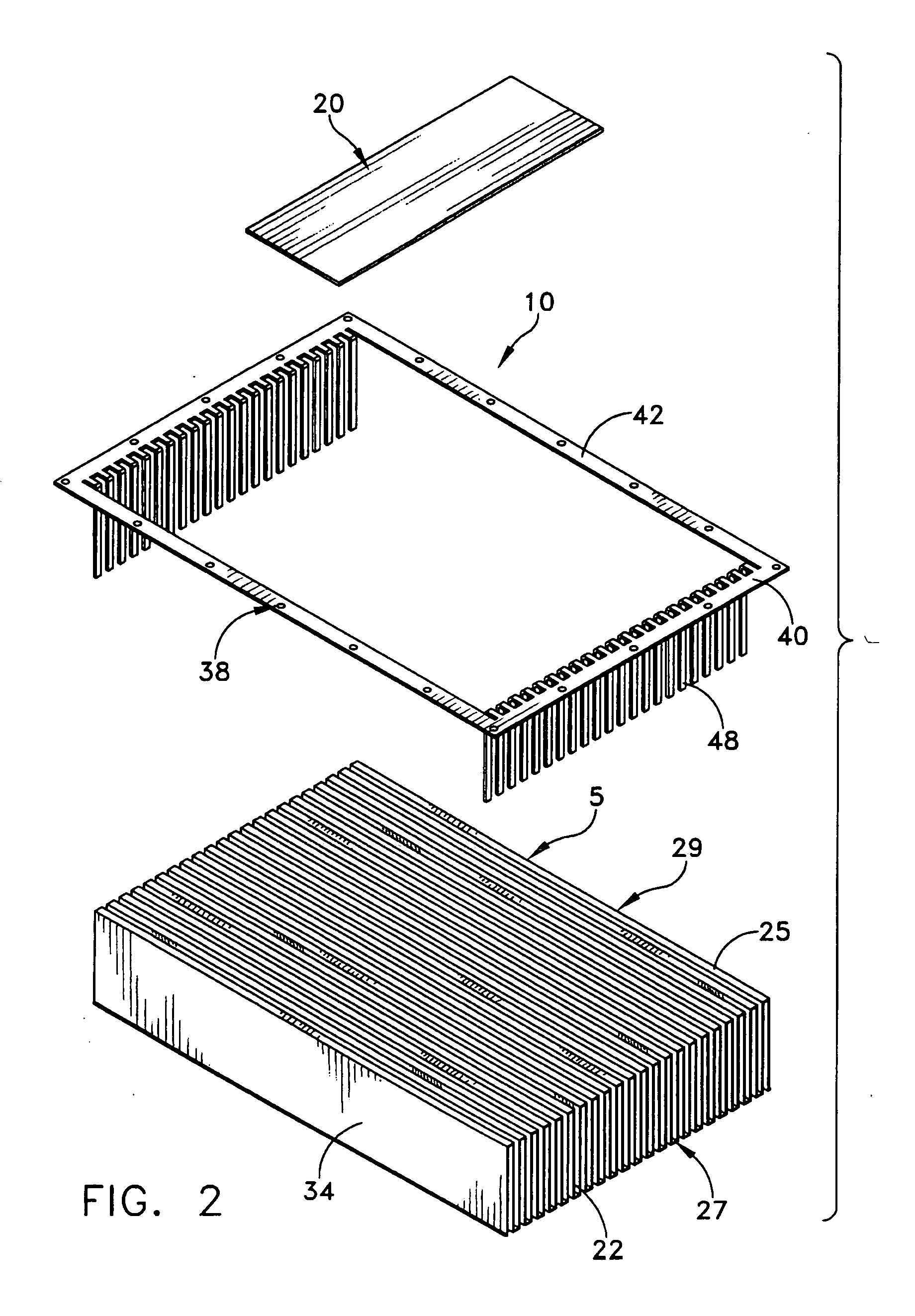
An air-to-air heat exchanger, is provided that comprises a folded fin core formed from a continuous sheet of thermally conductive material that has been folded into alternating flat ridges and troughs; an insert overlay having an opening including two sets of uniform fingers, wherein each finger has a portion protruding into and essentially filling each trough on one surface of the folded fin core; an inset region between each finger portion and the end edges of each trough; a sealant within each inset region sealably attaching the insert overlay to the folded fin core; and an air flow divider plate. Heat exchanger components are also provided.

Description

CROSS-REFERENCE TO RELATED PATENT APPLICATIONS [0001] This application is related to and claims priority from U.S. Provisional Patent Application No. 60 / 552,414, filed on Mar. 11, 2004.FIELD OF THE INVENTION [0002] The present invention generally relates to heat-exchangers, and more particularly to heat-exchangers of the type including plates arranged side-by-side and mutually parallel. BACKGROUND OF THE INVENTION [0003] Heat-exchangers having a plurality of mutually parallel plates, with channels that are adapted to carry at least one heat transfer fluid, are well known in the art. Such parallel plate devices are often formed by folding a continuous sheet of metal to yield a so called “folded-fin” heat exchanger. The plates in such prior art heat-exchangers sometimes form a circuit path for circulation of two independent fluids, in counterflow, from one end of the heat-exchanger to the other. The plates are often connected to one another at their longitudinal edges by longitudinal ...

Claims


Application Information

Patent Timeline
Patent Type & Authority Applications(United States)
IPC IPC(8): F28D7/02
CPCF28D9/0025F28F3/025F28F2240/00Y10S165/399F28F9/001F28F2220/00
Inventor THYRUM, GEOFFREY P.GARNER, SCOTT D.
Owner THERMAL
Learn More