Bridging clutch for a hydrodynamic clutch device enclosed by a housing

a technology of hydrodynamic clutch and bridging clutch, which is applied in the direction of rotary clutches, fluid couplings, gearings, etc., can solve the problems of bridging clutches that are found in axial connections to turbine wheels, unable to avoid at least partial premature wear of disks, and comparatively long reaction time of bridging clutches of this type, etc., to achieve favorable low-friction properties, low friction, and wear-free

Inactive Publication Date: 2005-09-15
ZF FRIEDRICHSHAFEN AG
View PDF9 Cites 9 Cited by
  • Summary
  • Abstract
  • Description
  • Claims
  • Application Information

AI Technical Summary

Benefits of technology

[0012] By locating the pretensioning element in the area of the friction surface or immediately adjacent thereto, very short routes can be obtained between at least one pretensioning element and at least one friction surface of the bridging clutch in the hydrodynamic clutch device. In cases where the friction surface is installed axially between the cover of the housing of the hydrodynamic clutch device and the piston of the bridging clutch, the pretensioning element and the friction surface can be brought very close together by locating the pretensioning element as well as the friction surface axially between the cover and the piston. In an arrangement of this type, the pretensioning element can be either radially inside or radially outside the friction surface, so that no axial space goes to waste; the pretensioning element will thus be in an area of the housing in which no component would otherwise be present.
[0014] For the transmission of higher torques, however, it is common practice to use bridging clutches with several friction surfaces, where in the conventional case at least one disk is provided axially between a first friction surface assigned to the piston and a second friction surface assigned to the cover of the housing. When several disks are used between these two friction surfaces, an intermediate disk is always interleaved between them. All of the disks and / or intermediate disks can be provided with friction linings. By increasing the number of disks or intermediate disks, the number of friction surfaces of the bridging clutch is also increased.
[0016] Because a nonrotatable connection of the piston to the turbine wheel will result in relative movement between the cover and the piston in the circumferential direction, this relative movement acts via the two pretensioning element mounts, i.e., the component support section on one side and the piston support section on the other side, on the pretensioning element located axially between them. For this reason, the pretensioning element according to the invention is provided with a slide device, by means of which relative movement between the two pretensioning element mounts can be accepted with minimal friction and essentially without wear. This slide device is preferably produced out of a material such as Teflon or Vespel with favorable low-friction properties.
[0017] The pretensioning element advantageously comprises a plurality of spring elements, which are either attached to the component support section of the first pretensioning element mount or form an integral part of that section. In the former case, the spring elements preferably extend at a tangent to an axis of rotation of the housing, and each accepts its own separate slide element. Through the arrangement of the spring and the slide element in the tangential direction and thus in the direction of the relative movement between the piston and the cover, an operating behavior characterized by extremely low wear can be obtained. In contrast, if the spring elements are formed as an integral part of the component support section, they are preferably oriented essentially in the radial direction, so that they can serve as support arms for a thrust ring, which connects the individual spring elements to each other. This thrust ring preferably cooperates with a slide device, designed essentially as a slip ring. As a result of the ring-shaped design of the thrust ring and of the slip ring, low wear can be expected during relative movement in the circumferential direction. Whereas, in the design in which a slide element is assigned to each individual spring element, there is little cutting waste of spring material and low-friction material, there are fewer components in the design with the thrust ring and the slip ring. In addition, less assembly work is required than for the design with individual spring elements, because each of these elements must be attached at one end to the component support section of the first pretensioning element mount, whereas measures must be taken at the other end to allow the permanent attachment of the slide element. When the spring elements are designed as an integral part of the component support element, however, there is no need for the previously mentioned attachment points or for the attachment of the slip ring to the thrust ring. The slip ring is therefore able to move relative to both the component support section and the piston support section, whereas, when a separate slide element is attached to each spring element, these elements accompany the movement of the component support section and are able to execute relative movement only with respect to the piston support section.

Problems solved by technology

The arrangement of the pretensioning element on the turbine hub and thus at a location far inside the disks in the radial direction is likely to be problem in the bridging clutch according to U.S. Pat. No. 4,177,885, in the sense that the pretensioning element must act on the disks via the piston, which thus serves as a speed reducer.
It is therefore impossible to avoid the at least partial premature wear of the disks.
Another disadvantage of this bridging clutch is to be found in its axial connection to the turbine wheel by way of the pretensioning element.
As a result of the absence of an axially operative pretensioning element, there is the problem that bridging clutches of this type take a comparatively long time to react during the clutch-engaging operation, this reaction time being easily on the order of 300-600 ms.
Another disadvantage is to be found in the loss of ability to control the piston, because, when the piston is disengaged, its position can be unstable if there is only a small pressure difference between the pressure space and the hydrodynamic circuit.
An instability of this type can have the effect that the piston is shifted abruptly and undesirably in the engaging direction, which can be perceived negatively in the vehicle as a jerk.

Method used


Image

  • Bridging clutch for a hydrodynamic clutch device enclosed by a housing
  • Bridging clutch for a hydrodynamic clutch device enclosed by a housing
  • Bridging clutch for a hydrodynamic clutch device enclosed by a housing

Examples


Embodiment Construction

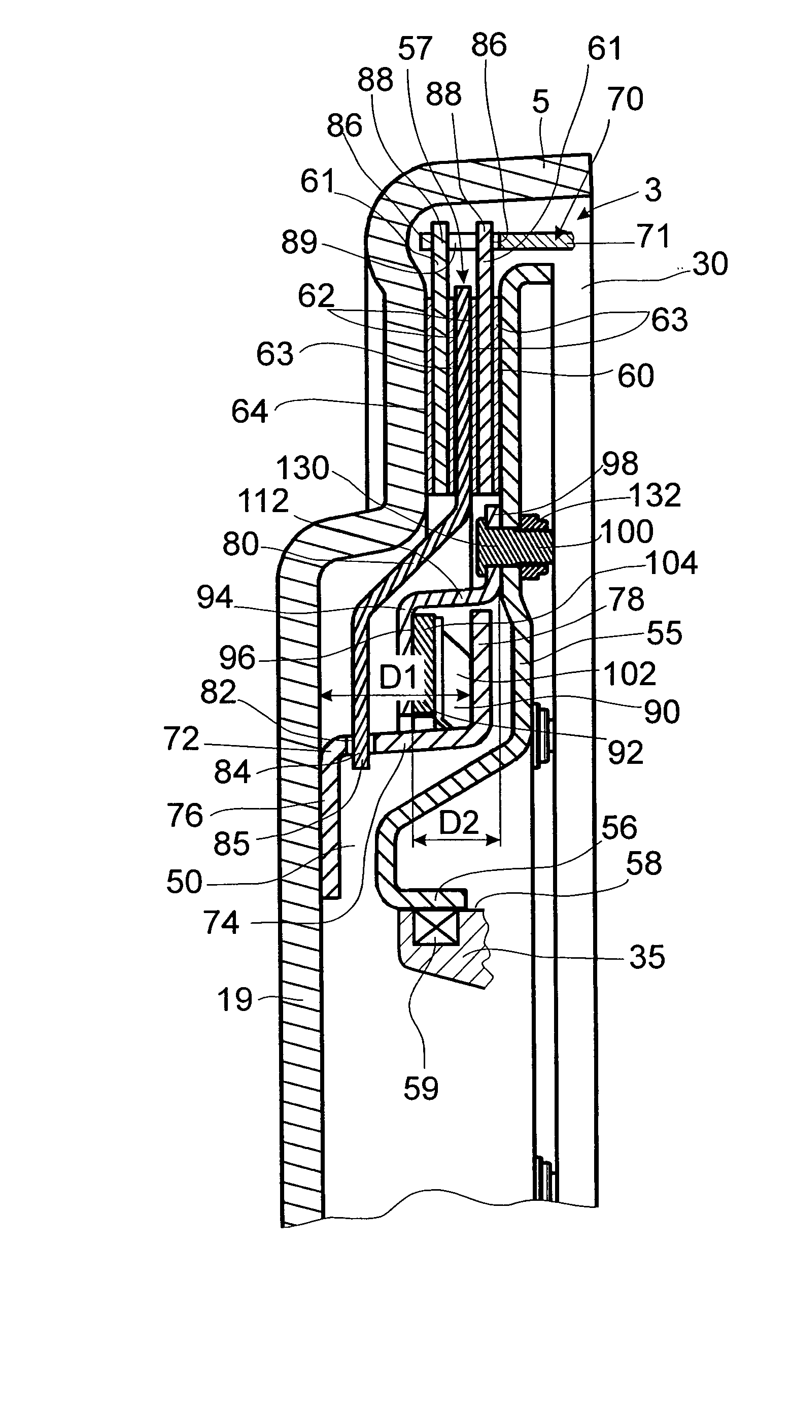
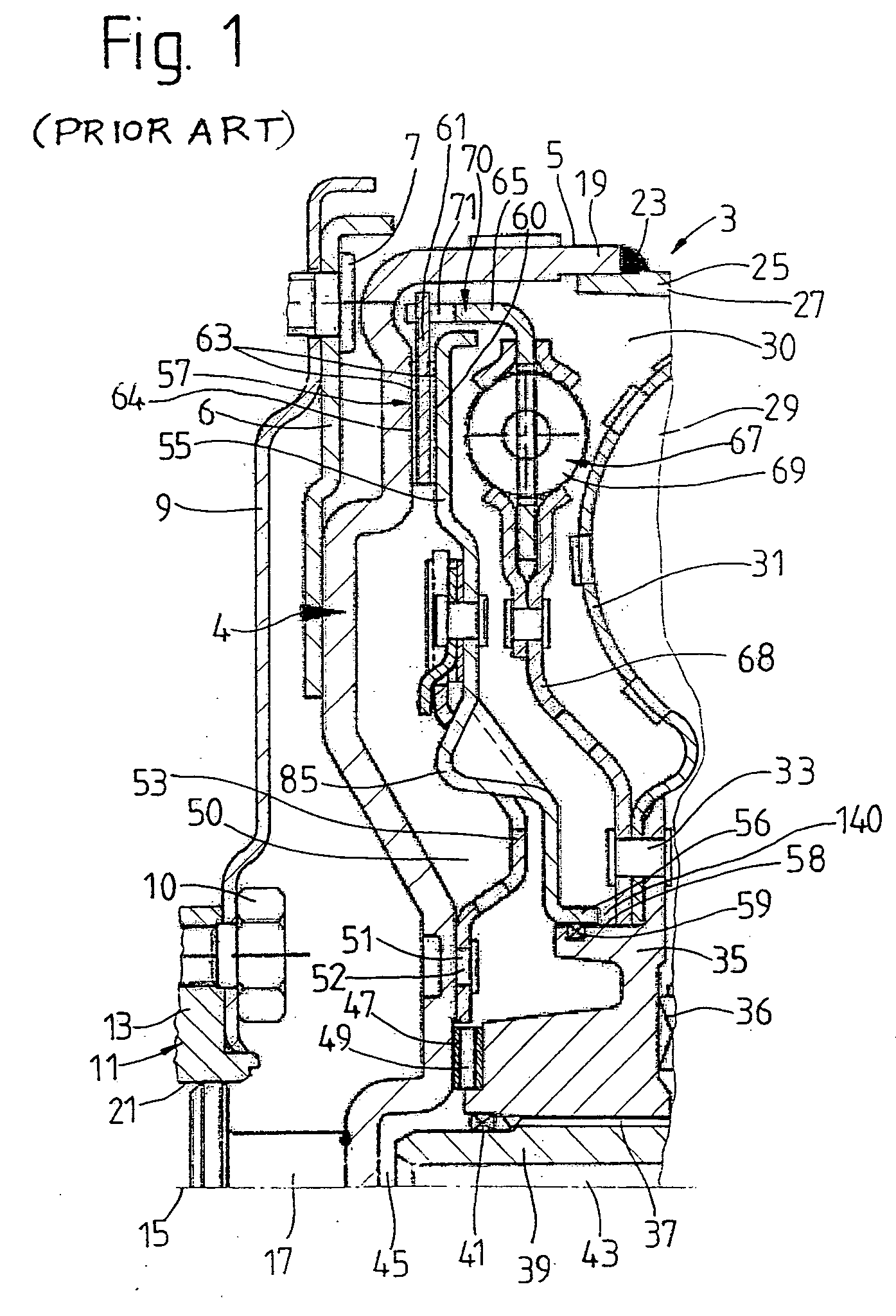
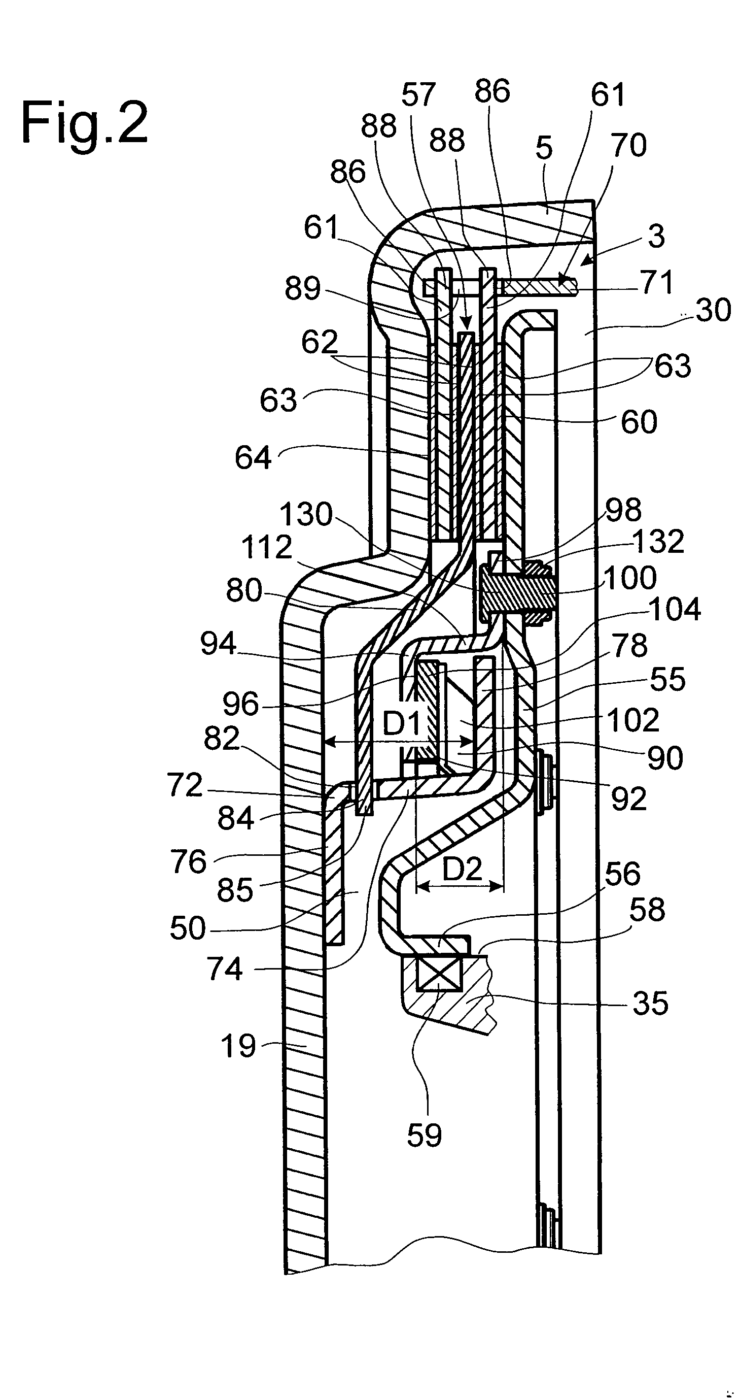
[0033] The hydrodynamic clutch device 3 shown in FIG. 1 embodies a design known according to the state of the art. This figure is intended to represent how a bridging clutch 57 can be installed in a hydrodynamic clutch device. Reference is made to FIGS. 2-9 with respect to the design of the bridging clutch 57 according to the invention, the bridging clutch 57 being illustrated in detail in those figures and described below.

[0034] According to FIG. 1, the hydrodynamic clutch device 3 has a housing 5, to which a tie plate 6 is attached by means of a weld 4; this plate can be connected by a plurality of mounting elements 7 and a connecting element 9 such as a flexplate to a drive element 11 such as the crankshaft 13 of an internal combustion engine for rotation in common.

[0035] The clutch device 3 also has a bearing journal 17 in the area of an axis of rotation 15; this journal is provided on a cover 19 of the housing 5 and is mounted in a centering guide 21 provided on the drive ele...


PUM


Abstract

A bridging clutch for a hydrodynamic clutch device includes a housing comprising a cover having a friction surface; a piston which can move axially with respect to the housing, the piston having a friction surface which faces the friction surface of the cover; a first pretensioning element mount fixed to the cover and having a first support section; a second pretensioning element mount fixed to the piston and having a second support section; and a pretensioning element supported axially between the first and second support sections for actuating the piston in a predetermined axial direction. A slide device located between the pretensioning element and the second support section permits sliding movement of the pretensioning element with respect to the second pretensioning element mount.

Description

BACKGROUND OF THE INVENTION [0001] 1. Field of the Invention [0002] The invention pertains to a bridging clutch for a hydrodynamic clutch device enclosed by a housing having a friction surface, a piston which can move axially with respect to the housing, the piston having a friction surface which faces the friction surface of the housing, and a pretensioning element supported axially between the piston and the housing for actuating the piston in a predetermined axial direction. [0003] 2. Description of the Related Art [0004] A bridging clutch for a hydrodynamic clutch device provided with a plurality of disks to form friction surfaces between a cover of the housing of the hydrodynamic clutch device and a piston is known from U.S. Pat. No. 4,177,885. The piston is mounted nonrotatably but with freedom of axial movement by way of its base on the hub of a turbine wheel and is subjected to pretension in the direction toward the disks by a pretensioning element in the form of an axial sp...

Claims


Application Information

Patent Timeline
Patent Type & Authority Applications(United States)
IPC IPC(8): F16H45/02
CPCF16H2045/0284F16H45/02
Inventor ZUEHL, CARSTEN
Owner ZF FRIEDRICHSHAFEN AG
Why Eureka
Try Eureka