Centrifuge purification filter apparatus and method

Inactive Publication Date: 2005-09-15
MANN HUMMEL GMBH
View PDF10 Cites 3 Cited by
  • Summary
  • Abstract
  • Description
  • Claims
  • Application Information

AI Technical Summary

Benefits of technology

[0012] In addition to forming the centrifuge apparatus housing with an integral spindle connection surface, a flow control valve bore which intersects the fluid inlet passage also may be integrally formed in the housing top portion, and the bore provided with a flow control valve which limits fluid flow into the top of the spindle until a predetermined inlet pressure is reached and, when inlet pressure is undesirably high, further limits flow into the centrifuge rotor. This feature provides a centrifuge purification filter which contains integrated automatic low pressure protection of the equipment it serves and over-pressure protection of the centrifuge purification filter itself. Further, by orienting the flow control valve bore diametrically opposite the housing mounting flanges, such an arrangement eases maintenance (and thereby further lowers operating costs) by making the flow control valve accessible for service without requiring removal of the entire housing from its mounts.
[0013] In this embodiment the housing inlet and housing outlet are formed as flat, co-planar flanges which include laterally-extending portions to accommodate fasteners extending therethrough. The use of flat, coplanar flanges, preferably with simple, flat gaskets between the flanges and corresponding mating surfaces on, for example, an engine block, greatly simplifies centrifuge purification filter housing mounting as compared to prior art mounting systems. For example, as shown in FIG. 1A and in FIG. 1B (cross-section view of FIG. 1A at plane A-A), the prior art housing has a stub tube 8 welded to the filter housing outlet 9 designed to mate with a corresponding o-ring-equipped, precision-machined bore 10. As compared to the present inve

Problems solved by technology

As can be seen from these examples, as developments have been made to increase efficiency of separation, and range of separability, the degree of structural complexity has also increased, with consequences of increased cost and, in some cases, increased complexity in equipment installation due to separator configuration requirements (e.g., hous

Method used


Image

  • Centrifuge purification filter apparatus and method
  • Centrifuge purification filter apparatus and method
  • Centrifuge purification filter apparatus and method

Examples


Example

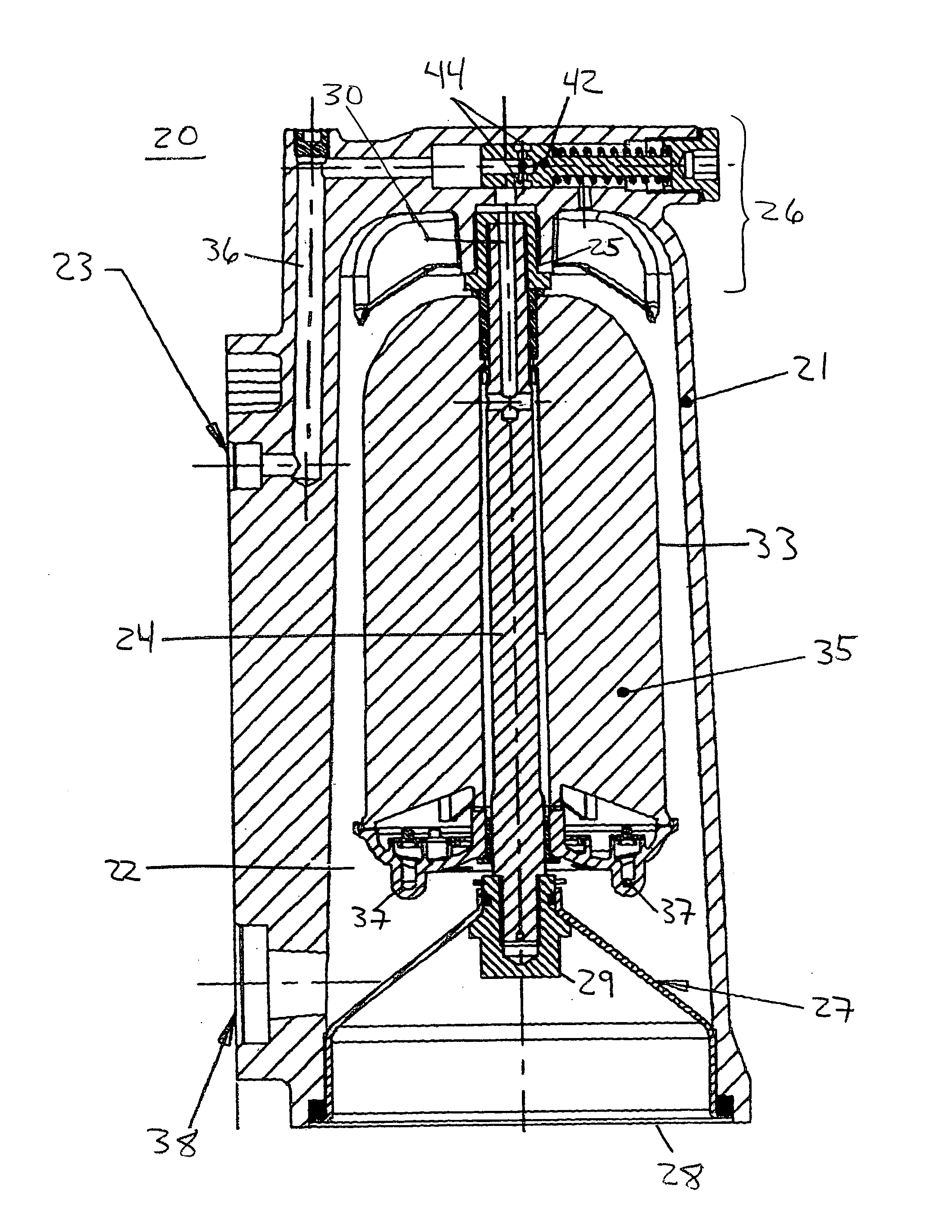
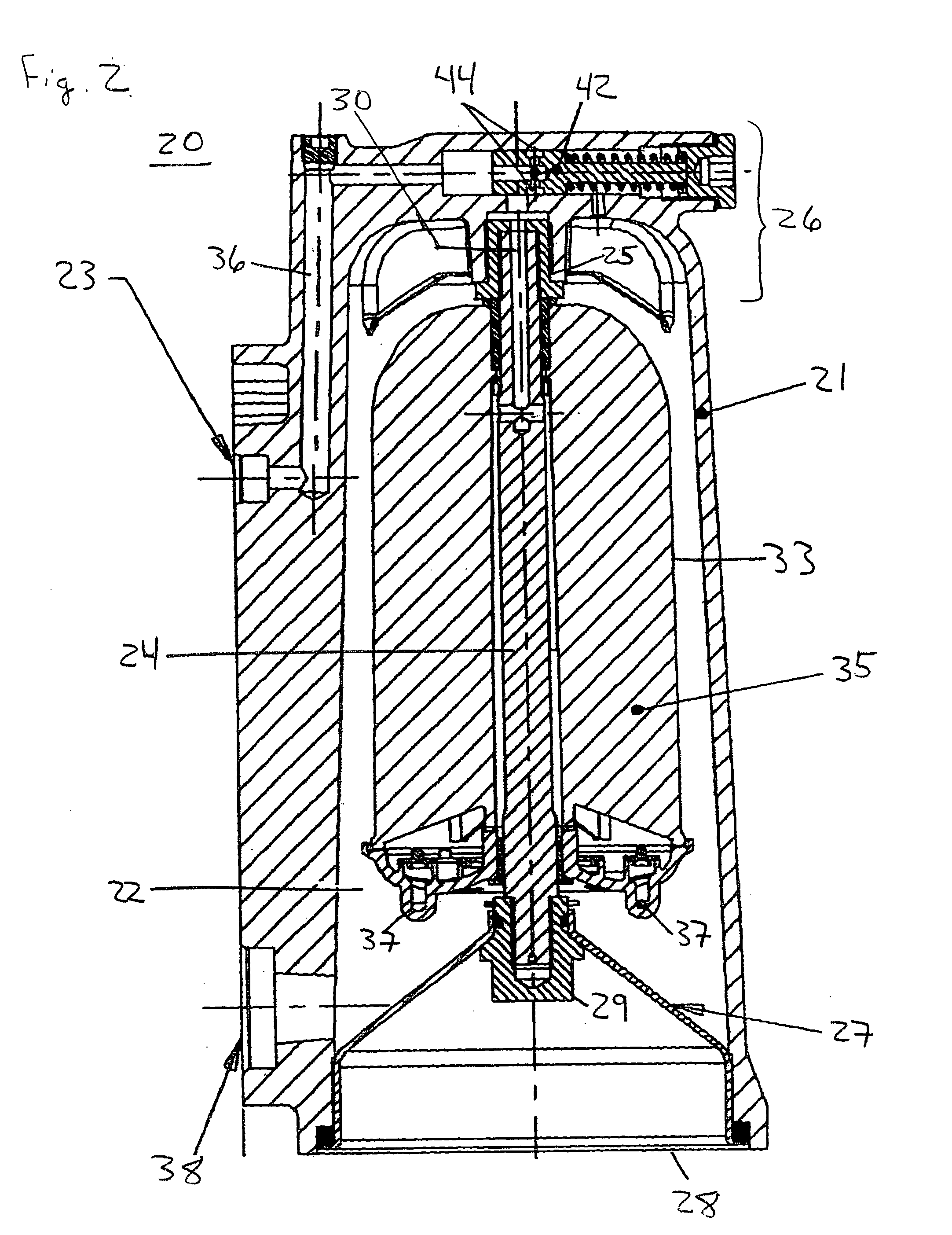
[0020]FIG. 2 is a first embodiment of the present invention, wherein a centrifuge purification filter apparatus 20 is provided a centrifuge purification filter apparatus with a housing 21 enclosing a purification volume 22. The housing includes a fluid inlet 23 to feed a contaminated liquid, in this embodiment, the lubricating oil of an engine, to a central spindle rod 24 attached to a threaded connection 25 either integrally formed in the integrally cast top portion 26 of the housing itself or, as shown in FIG. 1, formed in a bushing inserted into in the integrally formed top portion 26. The opposite end of the spindle is radially supported by a housing end cap 27. The housing end cap 27, which also closes off the bottom 28 of the housing, is retained by a nut 29 affixed to the spindle end.

[0021] The spindle is hollow at least between its inlet end 30 and a transverse outlet bore 31 part way down its length. Rotatably mounted on the spindle is a centrifuge rotor 32 which includes ...


PUM

PropertyMeasurementUnit
Pressureaaaaaaaaaa
Volumeaaaaaaaaaa
Speedaaaaaaaaaa

Abstract

A centrifuge purification filter is provided for purifying a fluid, such as engine lubricating oil. A housing with an integrally cast top portion contains a centrifuge rotor supported on a spindle, which in turn is supported at its top by the integrally formed housing top and retained and radially supported at its opposite end by a removable housing cover. The rotor includes a shell which receives contaminated fluid from the housing inlet via a hollow bore in the spindle. Fluid is discharged through tangential rotor outlet nozzles on the rotor cause the shell to rotate at high speed and thereby cause contaminants in the fluid to migrate to the shell wall. The integrally formed housing top portion may include a bore intersecting the inlet passage, wherein a flow control valve prevents flow into the rotor until inlet pressure reaches a predetermined level and in the event of excessive inlet pressure.

Description

BACKGROUND AND SUMMARY OF THE INVENTION [0001] The present invention relates to fluid purification, and in particular to centrifuge separation apparatus for separating contaminants from liquids, such as engine lubricants. [0002] Centrifugal separation is well known for use in applications, such as in the lubrication systems of vehicle internal combustion engines, as an efficient means for removing contaminants from the constantly recirculating liquid, such as small particulate matter arising from abrasion of the metallic components of the engine, decomposition of the lubricant and accumulated products of combustion over a long period of operation. [0003] An example of such centrifugal separation apparatus is shown in FIG. 1A. This type of centrifuge filter 1 is sometimes referred to as a sedimenting, solid-wall type in which separated solids are retained within a rotor housing 2 as a sediment against an impervious radially outer side wall thereof. Such centrifuge filters are distinc...

Claims


Application Information

Patent Timeline
IPC IPC(8): B01D35/00
CPCB04B11/04B04B5/005
Inventor SAMWAYS, ANDREWMILLS, JOHN L.
Owner MANN HUMMEL GMBH
Why Eureka
Try Eureka