Arc welding method

Inactive Publication Date: 2005-09-15
ABB (SCHWEIZ) AG
View PDF3 Cites 98 Cited by
  • Summary
  • Abstract
  • Description
  • Claims
  • Application Information

AI Technical Summary

Benefits of technology

[0007] A first object of the invention is to provide a method for controlling an arc welding equipment, which method enabling that the arc welding equipment may be controlled during

Problems solved by technology

Thus, at present, the settings of important welding process parameters used in robotic arc welding are found out experimentally by trial and error for every single welding task or welding condition, which is both time consuming and costly.
For example, in case of using parameters resulting in an undesired metal transfer mode the welded joint may be of a poor quality and the work piece may be destroyed.
One reason to the lack of knowledge about how the welding parameters effect

Method used


Image

  • Arc welding method
  • Arc welding method
  • Arc welding method

Examples


Embodiment Construction

[0074] In this application the wording “welding process” is used as a generic term of the main parts included in an arc welding operation and of the physical processes associated therewith which take place when an electric arc is generated between a wire (anode) and a work piece (cathode).

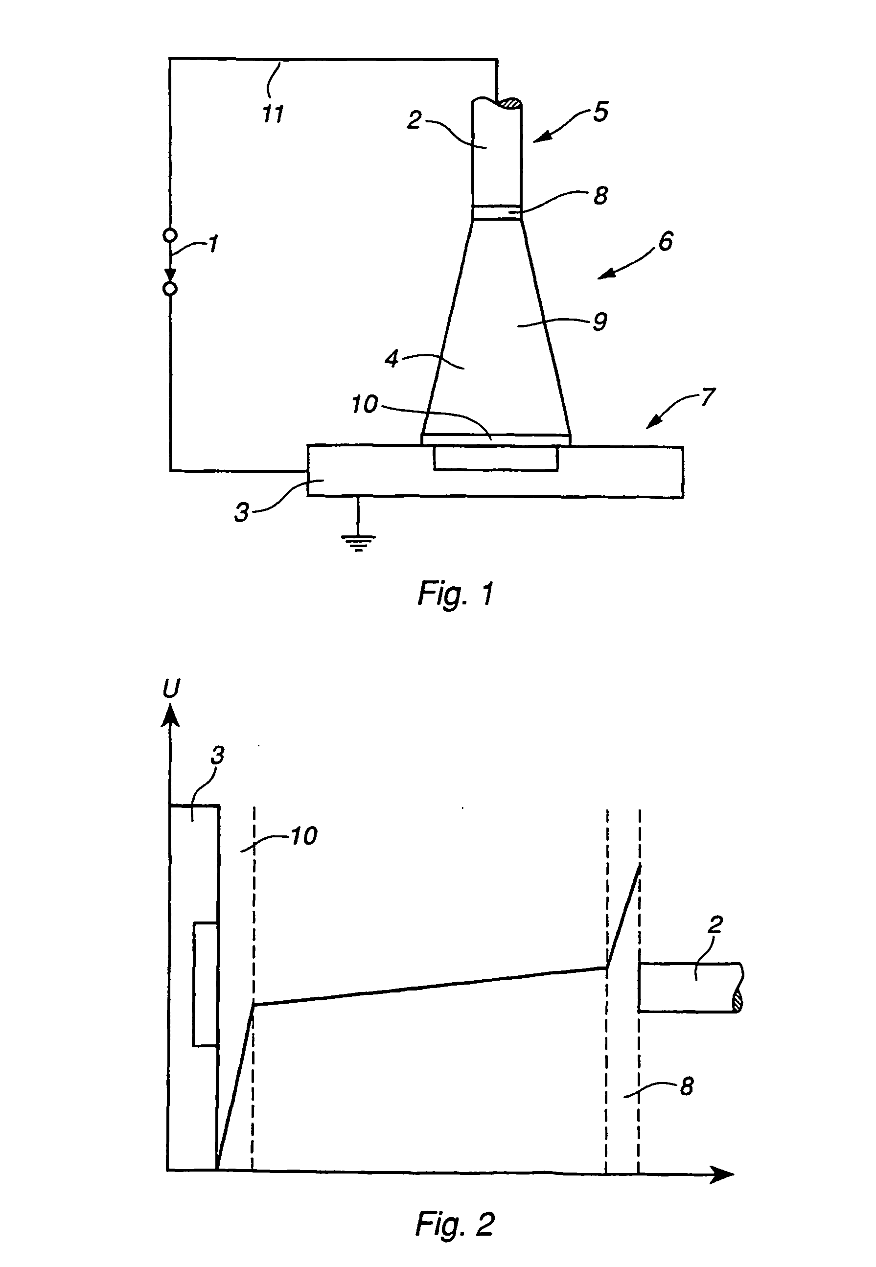
[0075] In FIG. 1 an arc welding process is schematically illustrated. The power source 1 is connected to a wire 2 and a work piece 3 to create a closed electric circuit by means of an arc 4 generated in the gap between the wire 2 and the work piece 3 with the purpose of transferring material from the wire 2 to the work piece 3.

[0076] The welding process may be divided in the following main parts: wire part 5, arc region part 6 and work piece part 7. Furthermore, the arc region part 6 may be divided in subparts, namely an arc-wire interaction region part 8, an arc column region part 9 and an arc-work piece interaction region part 10. All these parts contribute to the characteristics of the welding...


PUM

PropertyMeasurementUnit
Fractionaaaaaaaaaa
Timeaaaaaaaaaa

Abstract

A method for controlling an arc welding equipment (21) used in a welding operation and adjustable by varying at least one welding parameter value, comprising the steps of determining said at least one welding parameter while using a theoretical model (24) of the welding process associated with the welding operation, and controlling the operation of the welding equipment and the welding process associated therewith by using said at least one welding parameter for adjusting the welding equipment and a device comprising an arc welding equipment (21) used in a welding operation and adjustable by varying at least one welding parameter and an arrangement (22) for controlling the operation of the arc welding equipment, said control arrangement including a means (23) adapted to determine the value of said at least one welding parameter while using a theoretical model (24) of the welding process, and a member (25) adapted to control the operation of the welding equipment and the welding process associated therewith by using said at least one welding parameter value for adjusting the welding equipment.

Description

FIELD OF THE INVENTION AND PRIOR ART [0001] The present invention relates to a method for controlling an arc welding equipment used in a welding operation and adjustable by varying at least one welding parameter value, which method comprises the steps of: determining said at least one welding parameter value while using a theoretical model of the welding process associated with the welding operation and controlling the operation of the welding equipment and the welding process associated therewith by using said at least one welding parameter value for adjusting the welding equipment, to a method for simulating an arc welding process which method comprises the steps of: inputting data into a theoretical model representing the welding process and determining at least one welding parameter value of the welding process while using the theoretical model and the data input, with the purpose to simulate the welding process, and to a method for predicting the quality of a weld obtained from...

Claims


Application Information

Patent Timeline
IPC IPC(8): B23K9/095B23K9/10
CPCB23K31/006B23K9/1062
Inventor KADDANI, AHMEDRUAULT-KADDANI, PASCALEWINDECKER, ULRIKESKARIN, DICKLEMARINIER, PAVELZAHRAI, SAIDGU, CHUN-YUAN
Owner ABB (SCHWEIZ) AG
Why Eureka
Try Eureka