Control of detonative cleaning apparatus

a technology of detonating cleaning and cleaning equipment, which is applied in the direction of lighting and heating equipment, cleaning using liquids, applications, etc., can solve the problems of reducing efficiency and throughput, difficult direct access to the fouled surface, and large industrial equipment surface fouling

Inactive Publication Date: 2005-09-15
SHOCKSYST
View PDF8 Cites 33 Cited by
  • Summary
  • Abstract
  • Description
  • Claims
  • Application Information

AI Technical Summary

Benefits of technology

[0004] One aspect of the invention involves an apparatus for cleaning one or more surfaces within a vessel having a vessel wall separating a vessel exterior from a vessel interior and having a wall aperture. An elongate conduit has an upstream first end and a downstream second end and is positioned to direct a shockwave from the second end into the vessel interior. A source of fuel and oxidizer is coupled to the conduit to deliver the fuel and oxidizer to the conduit. An initiator is positioned to initiate a reaction of the fuel and oxidizer to produce the shockwave. A sensor senses one or more thermodynamic properties associated with the vessel. A control system is coupled to the initiator, the source, and the sensor.

Problems solved by technology

Surface fouling is a major problem in industrial equipment.
Such particulate build-up may progressively interfere with plant operation, reducing efficiency and throughput and potentially causing damage.
Often direct access to the fouled surfaces is difficult.

Method used


Image

  • Control of detonative cleaning apparatus
  • Control of detonative cleaning apparatus
  • Control of detonative cleaning apparatus

Examples


Embodiment Construction

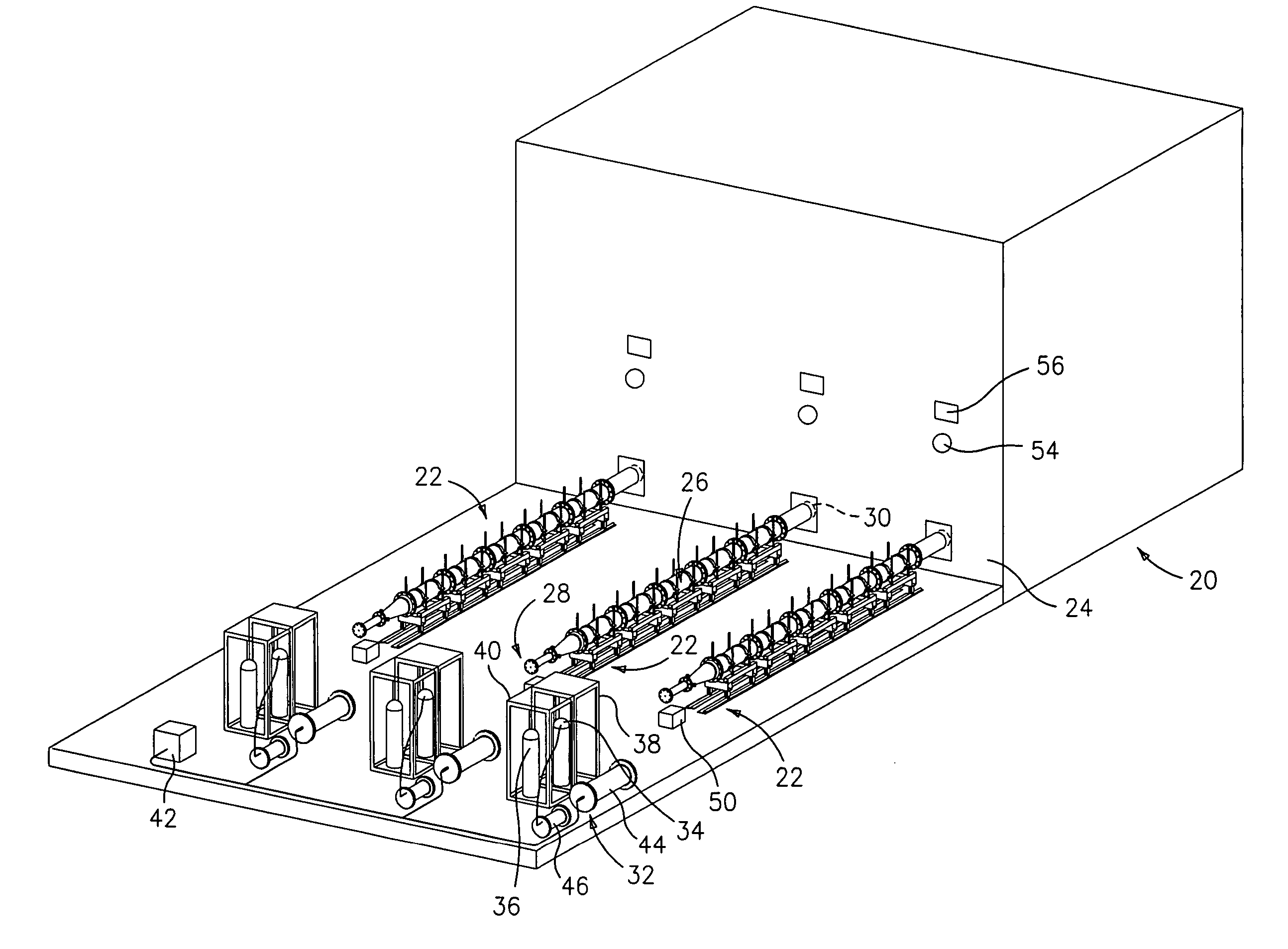
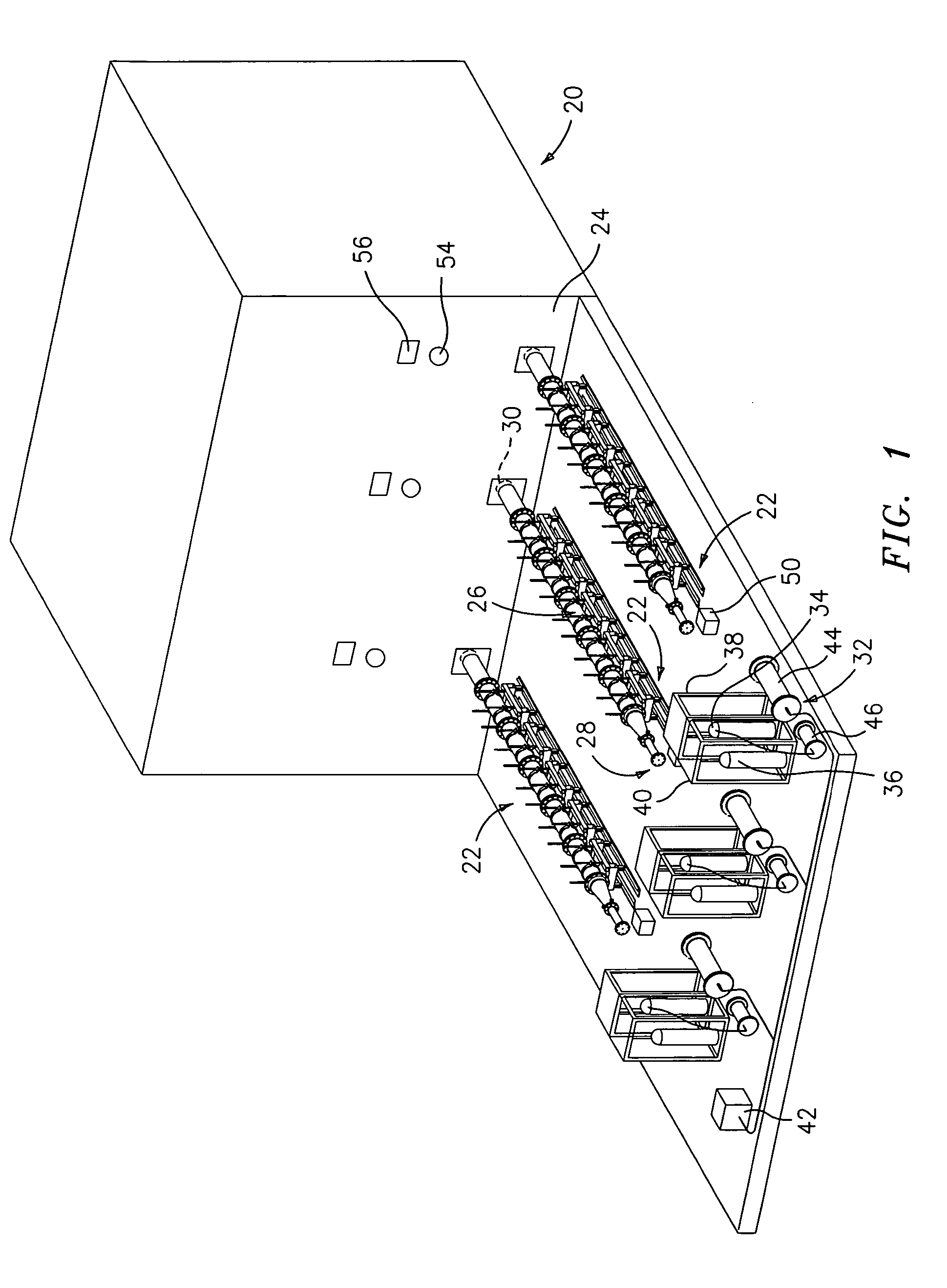
[0021]FIG. 1 shows a furnace 20 having an exemplary three associated soot blowers 22. In the illustrated embodiment, the furnace vessel is formed as a right parallelepiped and the soot blowers are all associated with a single common wall 24 of the vessel and are positioned at like height along the wall. Other configurations are possible (e.g., a single soot blower, one or more soot blowers on each of multiple levels, and the like).

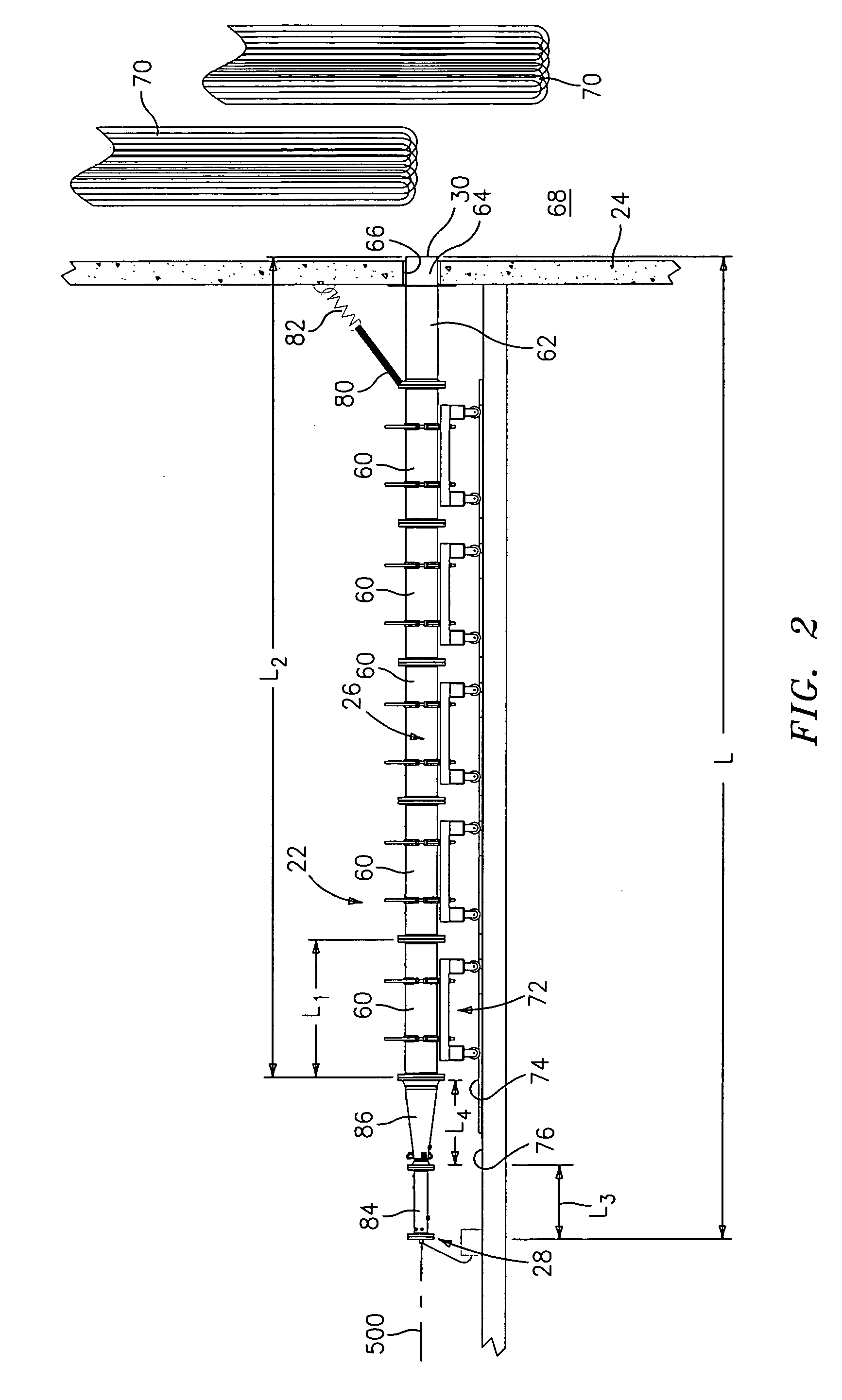
[0022] Each soot blower 22 includes an elongate combustion conduit 26 extending from an upstream distal end 28 away from the furnace wall 24 to a downstream proximal end 30 closely associated with the wall 24. Optionally, however, the end 30 may be well within the furnace. In operation of each soot blower, combustion of a fuel / oxidizer mixture within the conduit 26 is initiated proximate the upstream end (e.g., within an upstreammost 10% of a conduit length) to produce a detonation wave which is expelled from the downstream end as a shockwave along with a...


PUM


Abstract

A shockwave cleaning apparatus cleans one or more surfaces within a vessel. A sensor senses one or more thermodynamic properties associated with the vessel. A control system is coupled to an initiator and a fuel/oxidizer source to control the firing of the apparatus responsive to input from the sensor.

Description

FIELD OF THE INVENTION [0001] The invention relates to industrial equipment. More particularly, the invention relates to the detonative cleaning of industrial equipment. DESCRIPTION OF THE RELATED ART [0002] Surface fouling is a major problem in industrial equipment. Such equipment includes furnaces (coal, oil, waste, etc.), boilers, gasifiers, reactors, heat exchangers, and the like. Typically the equipment involves a vessel containing internal heat transfer surfaces that are subjected to fouling by accumulating particulate such as soot, ash, and minerals, more integrated buildup such as slag and / or fouling, and the like. Such particulate build-up may progressively interfere with plant operation, reducing efficiency and throughput and potentially causing damage. Cleaning of the equipment is therefore highly desirable and is attended by a number of relevant considerations. Often direct access to the fouled surfaces is difficult. Additionally, to maintain revenue it is desirable to m...

Claims


Application Information

Patent Timeline
Patent Type & Authority Applications(United States)
IPC IPC(8): B08B7/00B08B9/08F28G13/00
CPCB08B7/0007F28G13/00B08B9/08
Inventor HOCHSTEIN, JAMES R. JR.AARNIO, MICHAEL J.KENDRICK, DONALD W.BUSSING, THOMAS R.A.NIBLOCK, ROBERT R.
Owner SHOCKSYST
Why Eureka
Try Eureka