High recovery sonic gas valve

Active Publication Date: 2005-09-15
WOODWARD GOVERNOR CO
View PDF5 Cites 23 Cited by
  • Summary
  • Abstract
  • Description
  • Claims
  • Application Information

AI Technical Summary

Benefits of technology

[0006] The invention provides a gas valve design that achieves sonic flow at lower pressure ratios (P1/P2) in variable area critical (sonic) venturi designs than in conventional designs. The valve design provides a

Problems solved by technology

However, the downstream pressure measurement reduces the accuracy and reliability of the flow control due to the use of both upstream and downstream sensors.
However, the valve inlet pipe and outlet pipe are not in-line in many installations.
The flow coming in from a side rather than the centerline of the discharg

Method used


Image

  • High recovery sonic gas valve
  • High recovery sonic gas valve
  • High recovery sonic gas valve

Examples


Embodiment Construction

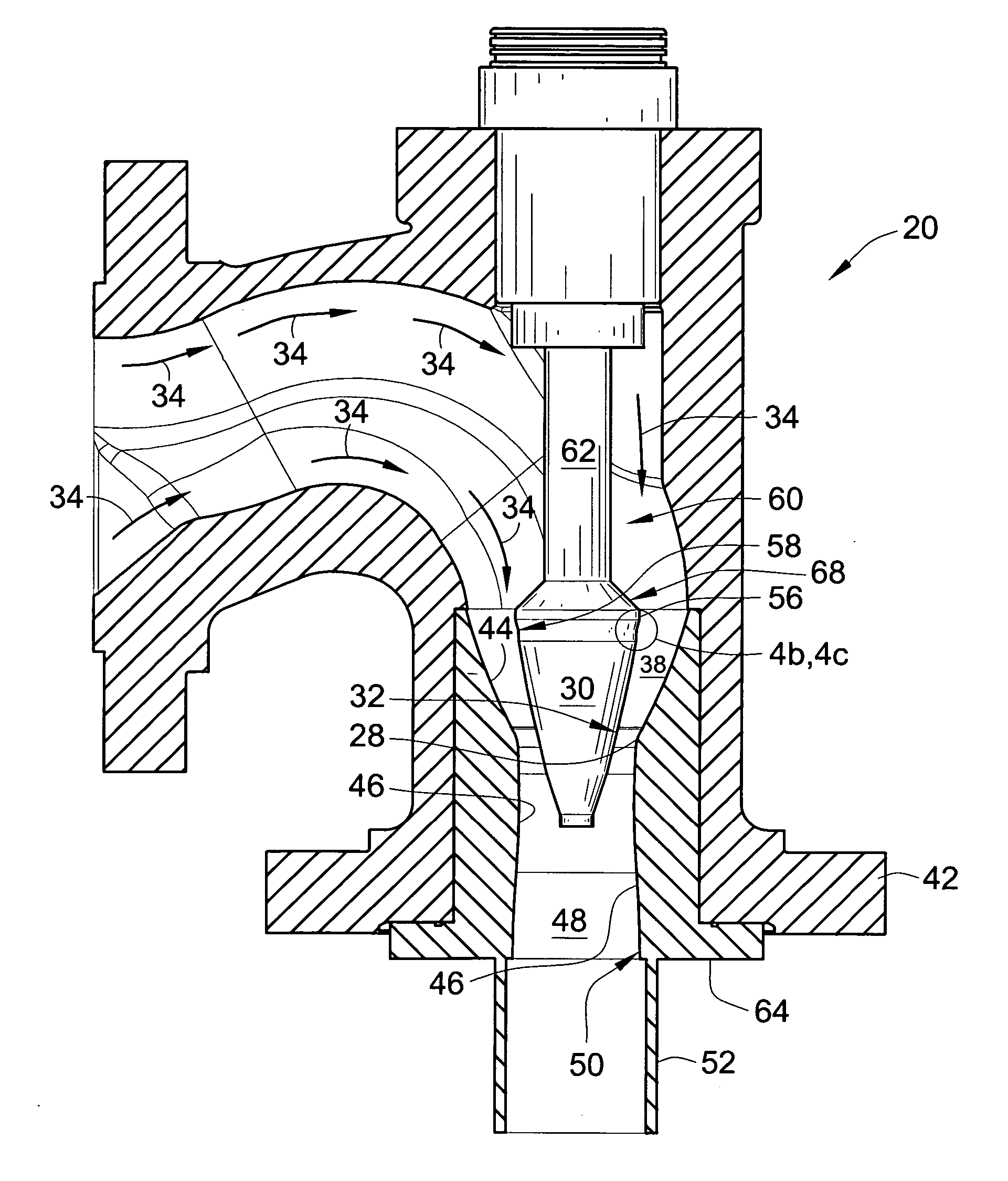
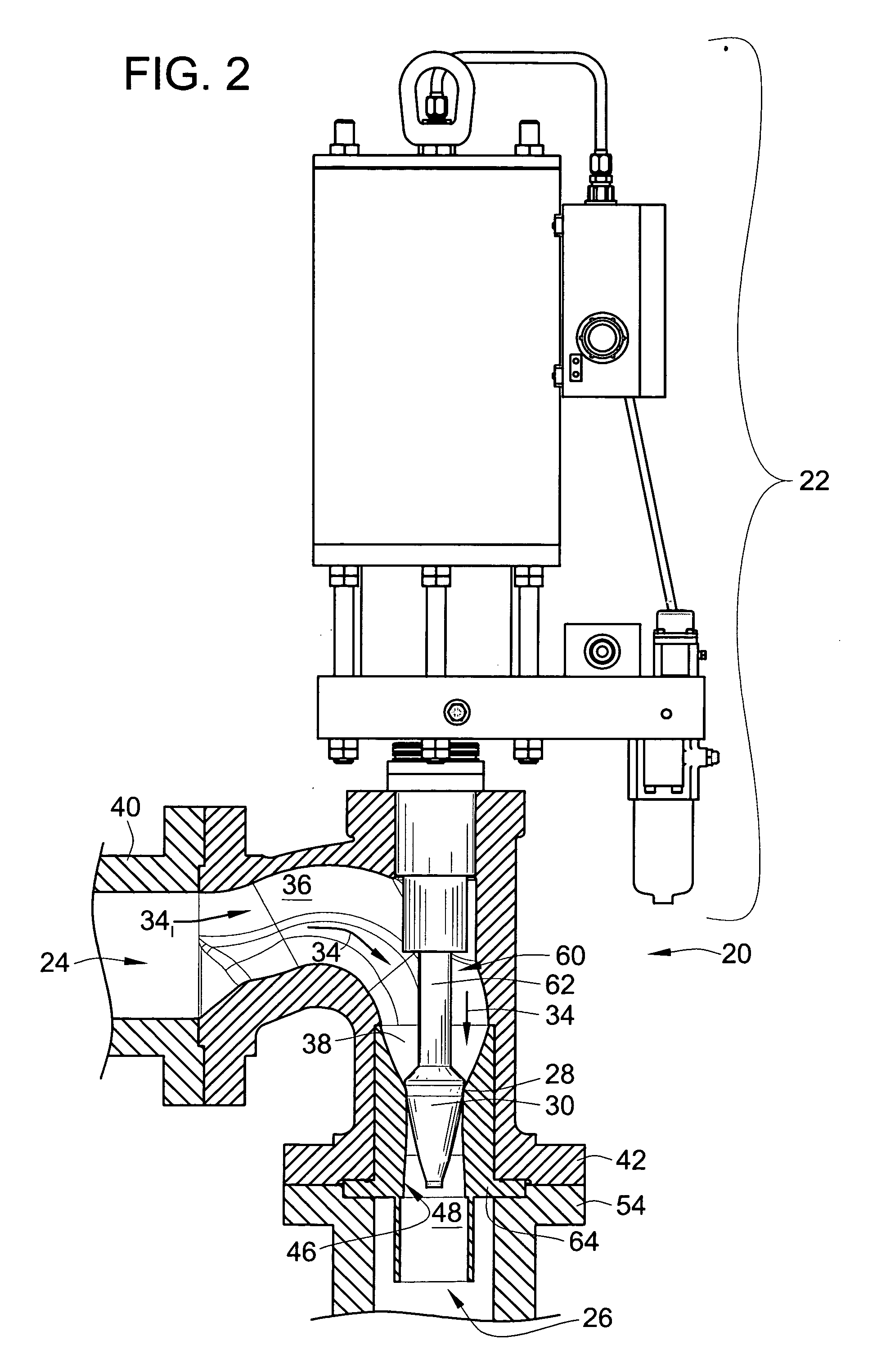
[0023] The present invention provides a gas control valve that controls the flow of gas (including air) and / or fuel for an industrial or gas turbine or other flow control system that cancels or greatly diminishes the effect on inlet flow entering orthogonal to the axis of the valve nozzle and diffuser. Several strategies shall be described to optimize the critical pressure ratio. The critical pressure ratio (P1 / P2) for a valve is defined as the ratio of inlet pressure (P1) to outlet pressure (P2) where the valve flow rate drops below some percentage of the sonic flow rate. All gas valves will provide sonic flow at Mach 1.0 in the throat of the valve with pressure ratios (P1 / P2) above approximately 2.0 (depending on gas properties). The valve described herein using the features described provides sonic flow throughout the nozzle throat for pressure ratios (P1 / P2) at or above approximately 1.04 in one embodiment. Some of these techniques may also be applied to other types of valves in...


PUM


Abstract

A high recovery sonic gas valve design with the inlet flow entering transverse and orthogonal to the outlet flow is presented. The configuration cancels the effects of the inlet flow entering orthogonal to the axis of the nozzle and diffuser. The inlet passage is curved in a manner to let the flow enter along the centerline of the nozzle and diffuser. The nozzle is contoured and provides upstream flow impedance. The diffuser is contoured with the area gradient varying from a low positive value at the nozzle throat then to a maximum value and finally dropping off significantly to near zero prior to the nozzle exit. The diffuser is nearly cylindrical and may extend past the valve outlet flange and protrude into adjacent piping.

Description

FIELD OF THE INVENTION [0001] The present invention relates generally to gas valves, and more particularly relates to sonic gas valves. BACKGROUND OF THE INVENTION [0002] Accurate control of mass flow rates is a requirement in many industries. For example, in the process industry, gas flow is controlled. In the gas turbine industry, mass flow rate is used to meter fuel into gas turbines. Mass flow is determined from the equation {dot over (m)}=ρVA where {dot over (m)} is the mass flow rate, ρ is the gas density, V is the velocity of the gas, and A is the cross-sectional area where the gas is flowing. [0003] Upstream pressure and temperature measurements are used to derive the gas density. To measure the velocity in subsonic valves, downstream pressure is also measured and velocity is derived based on the pressure differential of the upstream and downstream pressures. However, the downstream pressure measurement reduces the accuracy and reliability of the flow control due to the use ...

Claims


Application Information

Patent Timeline
IPC IPC(8): G01F1/34F01D25/00F02C7/22F02C7/232F16K1/12F16K1/38F16K1/52F16K47/02
CPCF16K1/38F16K47/00F16K1/52
Inventor BRINKS, BARRY T.GESSAMAN, JEFF A.SUELTER, BARRY
Owner WOODWARD GOVERNOR CO
Why Eureka
Try Eureka