
All-working-condition efficient fresh air ventilator for multi-stage heat pump heat recovery

A technology of heat recovery and full working conditions, which is applied in heat recovery systems, space heating and ventilation, and compression machines with reversible cycles, etc. It can solve the problems of limited applicable working conditions, increased costs, and high energy consumption of dehumidifiers.

Active Publication Date: 2021-03-16
TONGJI UNIV
View PDF8 Cites 10 Cited by
  • Summary
  • Abstract
  • Description
  • Claims
  • Application Information

AI Technical Summary

Problems solved by technology

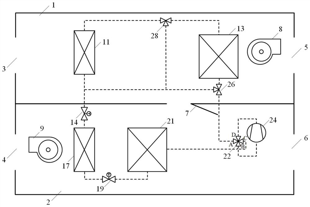
The traditional fresh air dehumidifier adopts a single-stage heat pump heat recovery cycle (for the system structure, refer to figure 1 ), the refrigerant evaporates and absorbs heat in the evaporator, cooling the passing fresh air to the dew point, and then condensing the water vapor in it to achieve the purpose of dehumidification. At this time, the evaporation temperature of the refrigerant is lower than the fresh air dew point temperature, resulting in Huge energy consumption and low energy efficiency
[0003] In addition, the existing technologies generally have the following deficiencies: (1) The applicable working conditions are limited, most of which provide simple fresh air and dehumidification modes, and it is difficult to achieve full coverage of fresh air cooling, heating, dehumidification, and internal circulation across different seasons
Patent CN201911412579.1 discloses an integral fresh air dehumidifier, which can realize fresh air mode and dehumidification mode by switching the flow channel, but there is no corresponding working mode in the transition season and winter, which is not suitable for fresh air supply throughout the year
(2) The comfort level is not good, the air supply temperature is unstable in summer, and different loads are not distinguished
If auxiliary electric heating is used, it will lead to complex structure, increased cost and decreased energy efficiency.
[0004] Patents CN202010522451.7, CN109000312A and CN201910949050.7 have cooling and dehumidification, heating and internal circulation modes by introducing coils and channel switching, but they do not distinguish between high and low loads in summer dehumidification conditions, and cannot always ensure fresh air supply wind temperature

Method used


Image

  • All-working-condition efficient fresh air ventilator for multi-stage heat pump heat recovery
  • All-working-condition efficient fresh air ventilator for multi-stage heat pump heat recovery
  • All-working-condition efficient fresh air ventilator for multi-stage heat pump heat recovery

Examples


Embodiment 1

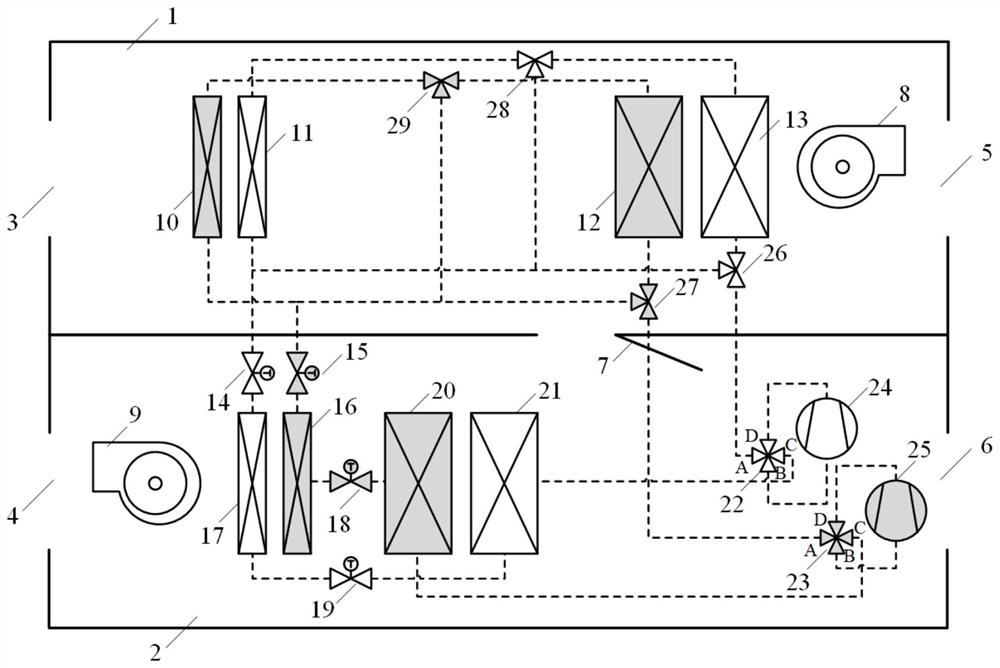
[0066] refer to figure 2 , a multi-stage heat pump heat recovery high-efficiency fresh air fan in this embodiment, the main structure includes a first air duct 1, a second air duct 2, a return air outlet 3, a supply air outlet 4, and an exhaust air outlet 5 , fresh air outlet 6, mixed air damper 7, exhaust fan 8, supply fan 9, subcooling coil 10, 11, exhaust coil 12, 13, first throttling device 14, 15, reheat coil 16 , 17, second throttling devices 18, 19, air supply coils 20, 21, four-way reversing valves 22, 23, compressors 24, 25, first bypass valves 26, 27, second bypass valve 28 , 29.

[0067] This embodiment includes two independent refrigerant loops (more than two refrigerant loops can be selected in the same way), a compressor 24 (25), a four-way reversing valve 22 (23), and a first bypass valve 26 (27), the refrigerant flow path of the exhaust coil 13 (12), the second bypass valve 28 (29), the refrigerant flow path of the subcooling coil 11 (10), the first throttli...

Embodiment 2

[0078] refer to Figure 10 , the system principle of this embodiment is similar to the operating mode and embodiment 1, the difference is that only one stage of reheating coil 17 is set, so that the subcooling section in the reheating coil 17 can be used in the cooling and dehumidification mode in summer and the heating / transition in winter The same air temperature gradient is matched in the intraseasonal circulation mode, and the temperature matching in different modes is more balanced.

[0079] refer to Figure 11 , this embodiment also provides a two-stage heat pump heat recovery fresh air fan, the air supply coil 21 (20) is provided with a two-stage heat exchanger, and the exhaust coil 13, the subcooling coil 11 and the reheating coil 17 are combined A single-stage heat exchanger. The system gives priority to the cooling and dehumidification mode in summer, and the air supply coil 21 (20) assumes the role of the evaporator, and the double evaporation temperature of the t...

Embodiment 3

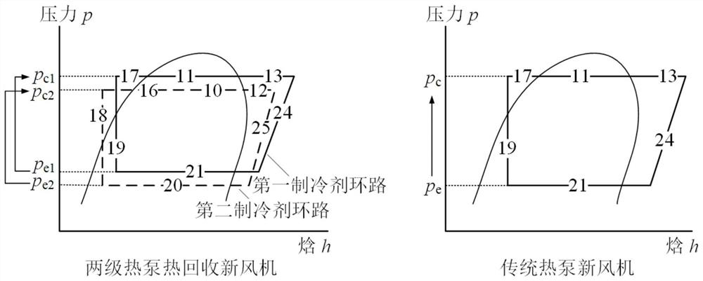
[0082] refer to Figure 12 , the system principle and operating mode of this embodiment are similar to that of Embodiment 1, the difference is that it shows the general construction form of multi-stage heat pump heat recovery (2-stage and above). Theoretically speaking, increasing the number of heat recovery stages of the heat pump can continuously reduce the pressure ratio of the heat recovery of the heat pump at all levels, thereby improving energy efficiency. In practical applications, the number of series used is determined after comprehensive consideration of structural complexity and system cost.

[0083] This example is cited to show that in the multi-stage nested refrigerant loop of the present invention, any increase or decrease in the number of heat recovery stages of the heat pump does not change its technical essence and should belong to the protection scope of this patent.


PUM


Abstract

The invention relates to an all-working-condition efficient fresh air ventilator for multi-stage heat pump heat recovery. The ventilator comprises a first air duct and a second air duct, and further comprises a multi-stage nested refrigerant loop, wherein the multi-stage nested refrigerant loop forms a temperature gradient on the evaporation side, bears more fresh air heat loads at a high evaporation temperature and bears more fresh air wet loads at a low evaporation temperature, therefore load gradient change distribution is formed; and the multi-stage nested refrigerant loop forms a temperature gradient on the condensation side, and a gradient condensation temperature matches the slippage of a return air temperature, so that a pressure ratio of each stage of refrigerant steam compressioncycle is reduced. Compared with the prior art, a multi-stage heat pump heat recovery cycle is arranged, so that the pressure ratio of each stage of refrigerant steam compression cycle is reduced, thepower consumption of a compressor is reduced, and the system energy efficiency can be effectively improved; and pertinence and comprehensiveness matching can be carried out on annual working conditions, and multiple modes of refrigeration and dehumidification in summer, heating in winter and internal circulation in transition seasons can be achieved.

Description

technical field [0001] The invention relates to an integral fresh air blower, in particular to a high-efficiency fresh air blower in all working conditions with multi-stage heat pump heat recovery. Background technique [0002] Many modern commercial and residential buildings have begun to introduce fresh air air conditioning systems to improve indoor air quality. The fresh air dehumidifier bears all the indoor humidity load and part of the heat load, and is often used in conjunction with indoor sensible heat treatment equipment (such as radiant air conditioning systems). The traditional fresh air dehumidifier adopts a single-stage heat pump heat recovery cycle (for the system structure, refer to figure 1 ), the refrigerant evaporates and absorbs heat in the evaporator, cooling the passing fresh air to the dew point, and then condensing the water vapor in it to achieve the purpose of dehumidification. At this time, the evaporation temperature of the refrigerant is lower tha...

Claims


Application Information

Patent Timeline
Patent Type & Authority Applications(China)
IPC IPC(8): F24F7/08F24F5/00F24F11/65F24F11/89F25B13/00F25B41/20F25B49/02
CPCF24F7/08F24F5/001F24F11/65F24F11/89F25B13/00F25B49/02Y02B30/52
Inventor 曹祥成家豪张春路
Owner TONGJI UNIV
Learn More