
Vehicle seat with cooling/heating device

a cooling/heating device and vehicle seat technology, applied in the direction of vehicle components, vehicle arrangements, chairs, etc., can solve the problems of reducing respiratory function, ozone having a detrimental influence on the body, frequent mechanical malfunctions, etc., to improve respiratory function, reduce fatigue of the person sitting, and improve air permeability and elasticity

Inactive Publication Date: 2005-09-15
NOH KI YEONG
View PDF20 Cites 160 Cited by
  • Summary
  • Abstract
  • Description
  • Claims
  • Application Information

AI Technical Summary

Benefits of technology

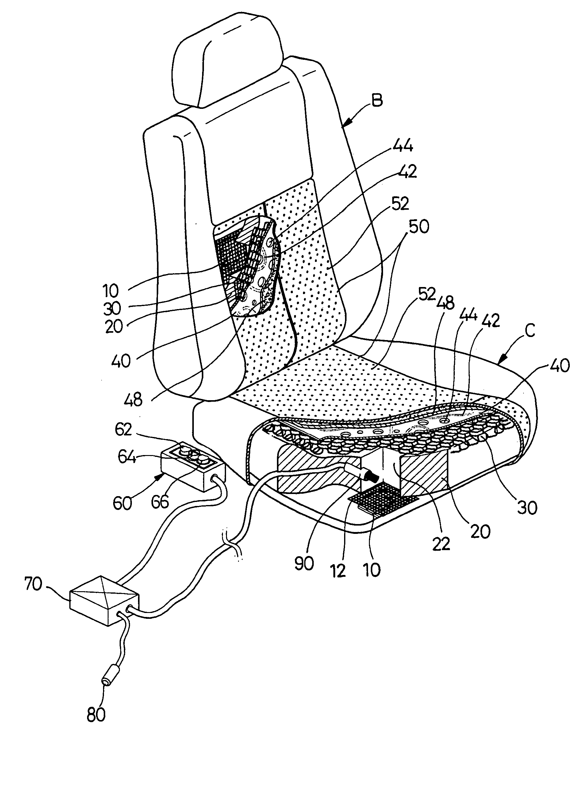
[0011] The present invention has been made to solve the above problems, and it is an object of the present invention to provide a vehicle seat designed to have a smaller number of more simple components, thereby lowering a possibility of mechanical malfunctions, compared with a conventional cooling / heating device of a vehicle, to have a structure allowing easy installation, thereby allowing easy installation to any kind of vehicle, and to have a heating function in the winter while having a ventilation or cooling function in the summer.
[0012] It is another object of the present invention to provide a vehicle seat, which is equipped with an anion generator to purify air within the vehicle in addition to the cooling / heating device, so that, when ventilating or heating the vehicle seat, purification of air can be performed according to a contaminated state of air within the vehicle, thereby enabling a person seated in the vehicle, including a driver and a passenger, to drive the vehicle in a more pleasant state.
[0015] The air-spreading layer may comprise hexagonal-shaped upper and lower nets with synthetic resin yarns connected between the upper and lower nets in a serpentine shape to provide air permeability and elasticity.
[0016] In accordance with another aspect of the present invention, there is provided a vehicle seat with a cooling / heating device, further comprising anion generators equipped in the air-supply pathways formed in the cushion member of the seat cushion and of the seat back to produce anions, and an air contamination-detecting sensor to detect a contaminated state of indoor air within the vehicle, such that driving of the anion generator can be automatically controlled by comparing an actual contamination degree detected by the air contamination-detecting sensor with a reference value previously determined in a controller. Accordingly, concurrently with cooling or heating the seat, a large number of anions are contained in the air discharged to the upper portion of the seat cushion and to the front portion of the seat back, thereby purifying indoor air and relieving fatigue of the person seated in the vehicle.

Problems solved by technology

However, the cooling / heating device of the vehicle seat according to the prior art, as described above, has problems in that mechanical malfunctions frequently occur due to its highly complicated structure, and in that it is not popularized and is equipped only in luxury vehicles, as an option, due to its high manufacturing costs.
Meanwhile, conventional anion generators produce a minute amount of ozone in the course of producing the anions, and ozone has a detrimental influence on the body due to its strong oxidizing power.
For instance, inhalation of ozone can destroy pulmonary cell structure, thus decreasing respiratory function.
Additionally, it can cause DNA mutation, resulting in damage to gene function, and causing cancer.
As a result, the conventional anion generators must be further provided with complicated devices for preventing ozone, concomitantly generated by the anion generator, from flowing out with the purified air, thereby complicating the structure of the anion generator, and increasing manufacturing costs of the anion generator.

Method used


Image

  • Vehicle seat with cooling/heating device
  • Vehicle seat with cooling/heating device
  • Vehicle seat with cooling/heating device

Examples


Embodiment Construction

[0024] Preferred embodiments will now be described in detail with reference to the accompanying drawings.

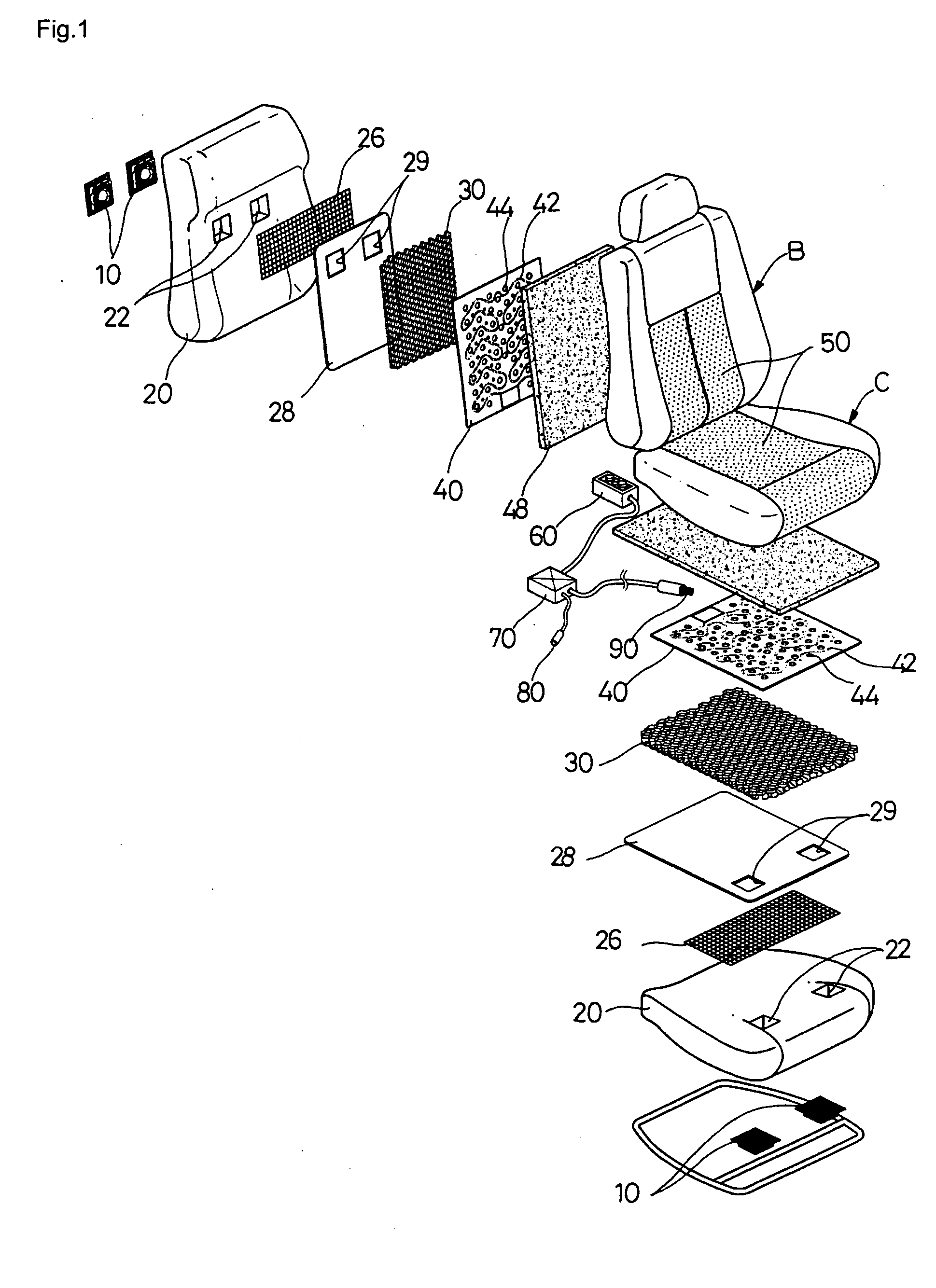
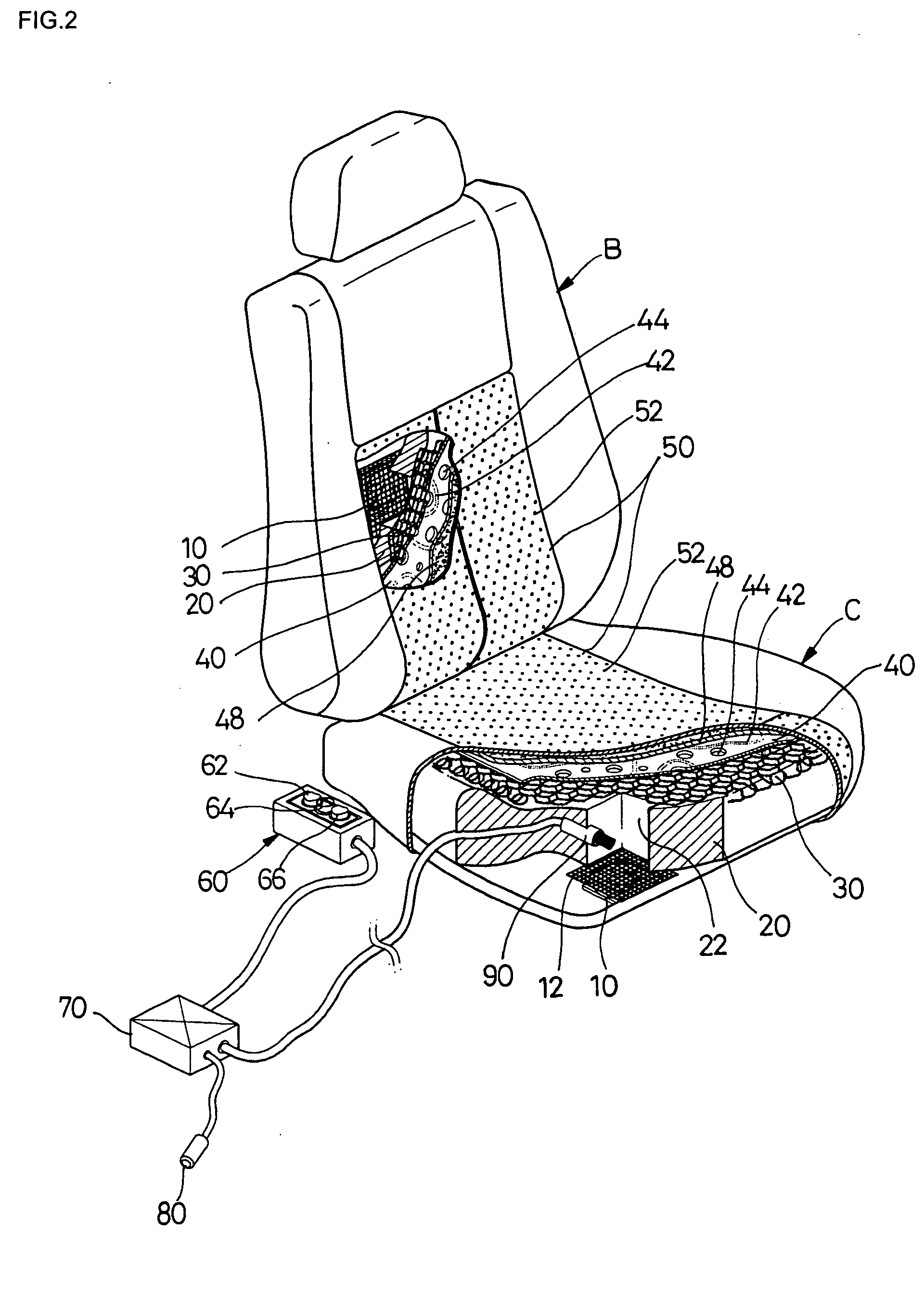
[0025] Referring to FIGS. 1 to 4, a vehicle seat including a seat cushion C and a seat back B with a cooling / heating device according to the present invention comprises: electric fans 10 respectively equipped in a lower portion of the seat cushion C and a rear portion of the seat back B to intake indoor air within the vehicle into the seat cushion and the seat back; cushion members 20 respectively provided in the seat cushion C and in the seat back B and formed with air-supply pathways 22 to supply air induced from the seat cushion C and the seat back B to an upper portion of the seat cushion C and to a front portion of the seat back B; air-spreading layers 30 respectively layered on an upper portion of the cushion member 20 provided in the seat cushion C and on a front portion of the cushion member 20 provided in the seat back B to spread air induced through each of the air-sup...


PUM


Abstract

Disclosed herein is a vehicle seat with a cooling / heating device. The vehicle seat comprises electric fans respectively equipped in a lower portion of a seat cushion and a rear portion of a seat back to intake indoor air within the vehicle, cushion members respectively provided in the seat cushion and the seat back and formed with air-supply pathways to supply air induced from the seat cushion and the seat back to an upper portion of the seat cushion and to a front portion of the seat back, air-spreading layers respectively layered on an upper portion of the cushion member provided in the seat cushion and on a front portion of the cushion member provided in the seat back to spread air induced through each of the air-supply pathways, heating pads respectively layered on the air-spreading layers, with a heating line disposed therein, and with a plurality of ventilation holes punctured through each of the heating pads between serpentine sections of the heating line along the heating line, and seat covers respectively layered on the heating pads and having a plurality of air discharge openings formed on the surface of the seat cover.

Description

[0001] This application claims priority of Korean Patent Application Nos. 2004-6264 filed on Mar. 9, 2004 and 2004-24400 filed on Aug. 26, 2004. BACKGROUND OF THE INVENTION [0002] 1. Field of the Invention [0003] The present invention relates to a vehicle seat with a cooling / heating device, and more particularly to a vehicle seat, which comprises electric fans to blow air into a seat cushion and a seat back, and a heating pad with a heating line disposed in the vehicle seat to generate heat when electric power is applied to the heating line, in order that the vehicle seat can be comfortably and pleasantly employed regardless of season by allowing the vehicle seat to perform a ventilation function to cool a driver or a passenger in the summer and a heating function to warm the driver or the passenger in the winter, thereby allowing the seated driver or passenger to selectively cool (ventilate) or heat the seat, as necessary. [0004] In addition to the cooling / heating device, the vehic...

Claims


Application Information

Patent Timeline
Patent Type & Authority Applications(United States)
IPC IPC(8): A47C7/72
CPCB60N2/5642B60N2/5685B60N2/5678B60N2/5657
Inventor NOH, KI-YEONG
Owner NOH KI YEONG
Learn More