Image-taking apparatus

Inactive Publication Date: 2005-09-15
KONICA MINOLTA PHOTO IMAGING
View PDF2 Cites 20 Cited by
  • Summary
  • Abstract
  • Description
  • Claims
  • Application Information

AI Technical Summary

Benefits of technology

[0011] An object of the present invention is to provide an image-taking apparatus incorporating a zoo

Problems solved by technology

However, with the constructions disclosed in Publication 1, it is difficult to achieve compactness while maintaining high optical performance.
Here, however, the optical power of the first lens element is too weak to achieve satisfactory compactness.
This, disadvantageo

Method used


Image

  • Image-taking apparatus
  • Image-taking apparatus
  • Image-taking apparatus

Examples


examples

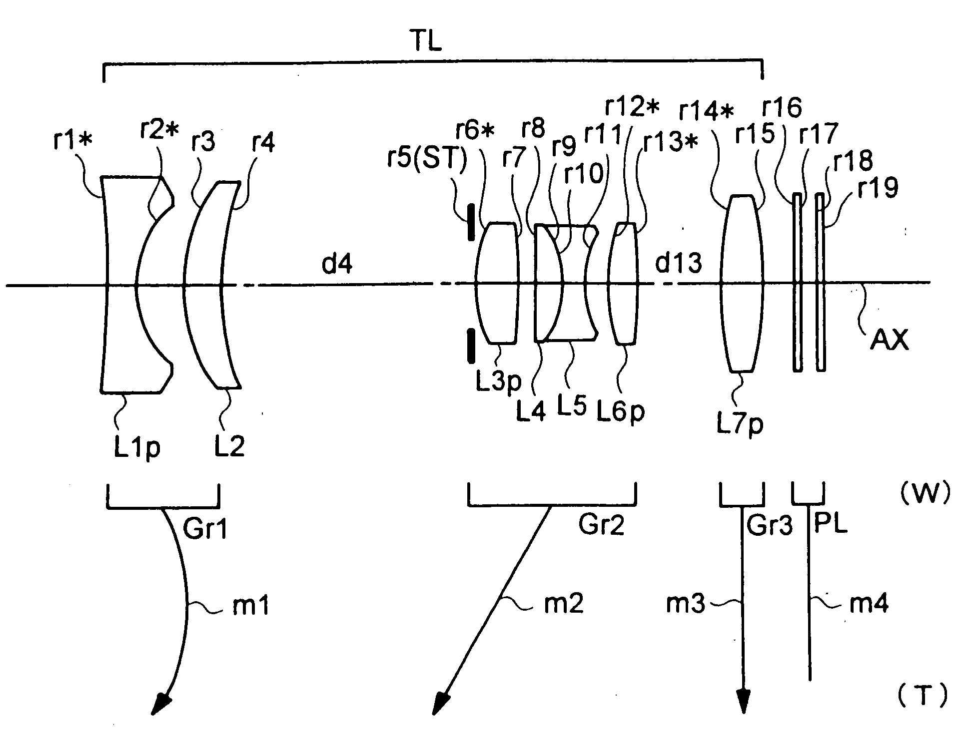
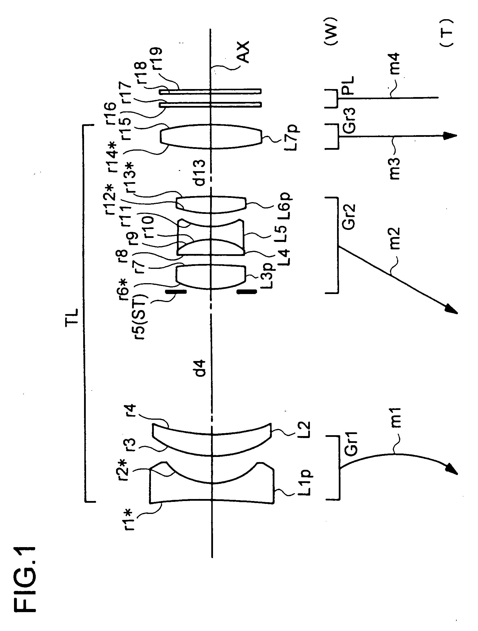
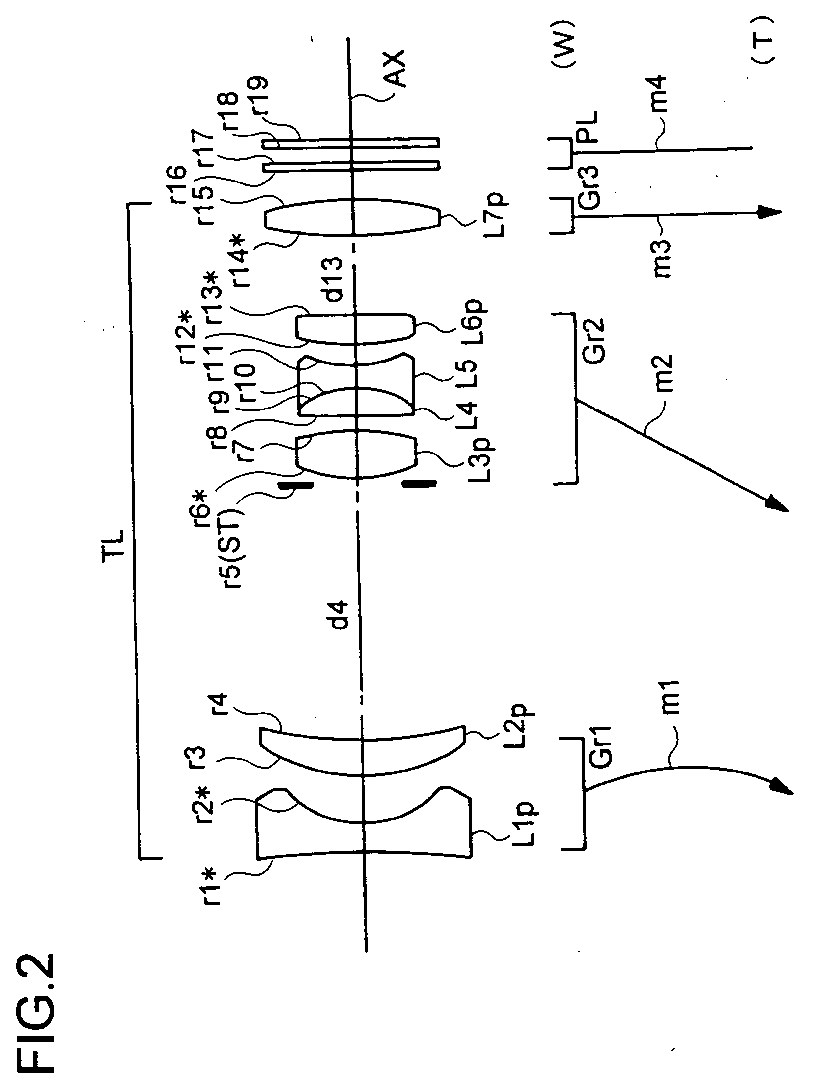
[0094] Hereinafter, the construction and other features of practical examples of the zoom lens system used in an image-taking apparatus embodying the present invention will be presented with reference to their construction data and other data. Examples 1 to 6 presented below are numerical examples corresponding to the first to sixth embodiments, respectively, described hereinbefore, and therefore the optical construction diagrams (FIGS. 1 to 6) of the first to sixth embodiments also show the lens construction of Examples 1 to 6, respectively.

[0095] Tables 1 to 6 show the construction data of Examples 1 to 6, respectively. Tables 7 and 8 show the values of the conditional formulae and the data related thereto as actually observed in each example. In the basic optical construction (with “i” representing the surface number) presented in each of Tables 1 to 6, ri (i=1, 2, 3, . . . ) represents the radius of curvature (in mm) of the i-th surface from the object side, di (i=1, 2, 3, . . ...


PUM


Abstract

A zoom lens system for forming an optical image of a subject on the image-sensing surface of an image sensor has three lens units, namely, from the object side thereof, a first lens unit having a negative optical power, a second lens unit having a positive optical power, and a third lens unit having a positive optical power, and achieves zooming by varying the distances between the individual lens units in such a way that, during zooming from the wide-angle end to the telephoto end, the distance between the first and second lens units decreases. The first lens unit is composed of two or more lens elements, and the first lens element, i.e., the lens element disposed at the object-side end of the first lens unit, and the last lens element, i.e., the lens element disposed at the image-side end of the third lens unit, are plastic lens elements. Moreover, a prescribed conditional formula is fulfilled.

Description

[0001] This application is based on Japanese Patent Application No. 2004-069335 filed on Mar. 11, 2004, the contents of which are hereby incorporated by reference. BACKGROUND OF THE INVENTION [0002] 1. Field of the Invention [0003] The present invention relates to an image-taking apparatus, and more particularly to an image-taking apparatus that takes in an image of a subject optically through a zoom lens system and then outputs it in the form of an electrical signal by means of an image sensor, and among others to an image-taking apparatus provided with a compact, lightweight zoom lens system. [0004] 2. Description of the Prior Art [0005] Today, digital cameras are quite popular. Digital cameras dispense with silver-halide film, and use instead an image sensor such as a CCD (charge-coupled device) or CMOS (complementary metal oxide semiconductor) sensor to convert an optical image into an electrical signal so that the optical image can be recorded and transferred in the form of dig...

Claims


Application Information

Patent Timeline
IPC IPC(8): G02B15/163G02B13/18G02B15/14G02B15/20H04N5/225H04N101/00
CPCH04N5/2254G02B15/177G02B15/143507
Inventor NOSE, HIROMICHITERADA, MAMORUMASUI, ATSUO
Owner KONICA MINOLTA PHOTO IMAGING
Why Eureka
Try Eureka