System and method for mixing water and non-aqueous materials using measured water concentration to control addition of ingredients

a technology of measuring water concentration and mixing system, which is applied in the direction of non-electric variable control, process and machine control, instruments, etc., can solve the problems of inability to accurately control the ratio of non-aqueous materials to water, the disadvantage of adding equipment and flow lines to the mixing system, and the density-based control system not working well. , to achieve the effect of reducing the space required for operating equipment, and reducing the amount of operating equipmen

Active Publication Date: 2005-09-15
HALLIBURTON ENERGY SERVICES INC
View PDF30 Cites 70 Cited by
  • Summary
  • Abstract
  • Description
  • Claims
  • Application Information

AI Technical Summary

Benefits of technology

[0006] The present invention is directed to a system and method that eliminates or at least minimizes the drawbacks of prior volumetric mixing systems.
[0009] The system and method according to the present invention has application in either a batch mixing process or a continuous mixing process. In a batch process, a tub of any volume can be mixed to the proper ratio of water and non-aqueous material, and then discharged. To accomplish a continuous mixing process, the mixing tub is initially filled with a mixture that has the proper ratio of water and non-aqueous material (solid or liquid) as measured by the concentration sensor. Then the mixture can be discharged from the mixing tub while simultaneously adding new ingredients to the mixing tub in a controlled manner that maintains the ratio of water and non-aqueous material in the tub, thus maintaining a continuous process. A continuous process allows the mixing of large volumes using a small mixing tub.
[0010] The advantages of measuring the water concentration directly include reduced pieces of operating equipment, smaller space required for operating equipment, lower cost, and simplified controls. The present invention thus provides a system that is less expensive and easier to retrofit on existing equipment. Additional features and advantages of the present invention will be readily apparent to those skilled in the art upon a reading of the description of the exemplary embodiments, which follows.

Problems solved by technology

A drawback with such slurries is that below certain densities, the ratio of non-aqueous material to water can change significantly with only minor changes in density.
In these situations, density-based control systems do not work well.
While the above described volumetric mixing systems generally work well, they have the disadvantage of adding equipment and flow lines to the mixing systems.
In many applications, particularly offshore, space is not available for the additional equipment.
These systems also become less accurate as the size of the mixing tub increases, sometimes limiting their application.

Method used


Image

  • System and method for mixing water and non-aqueous materials using measured water concentration to control addition of ingredients
  • System and method for mixing water and non-aqueous materials using measured water concentration to control addition of ingredients
  • System and method for mixing water and non-aqueous materials using measured water concentration to control addition of ingredients

Examples


Embodiment Construction

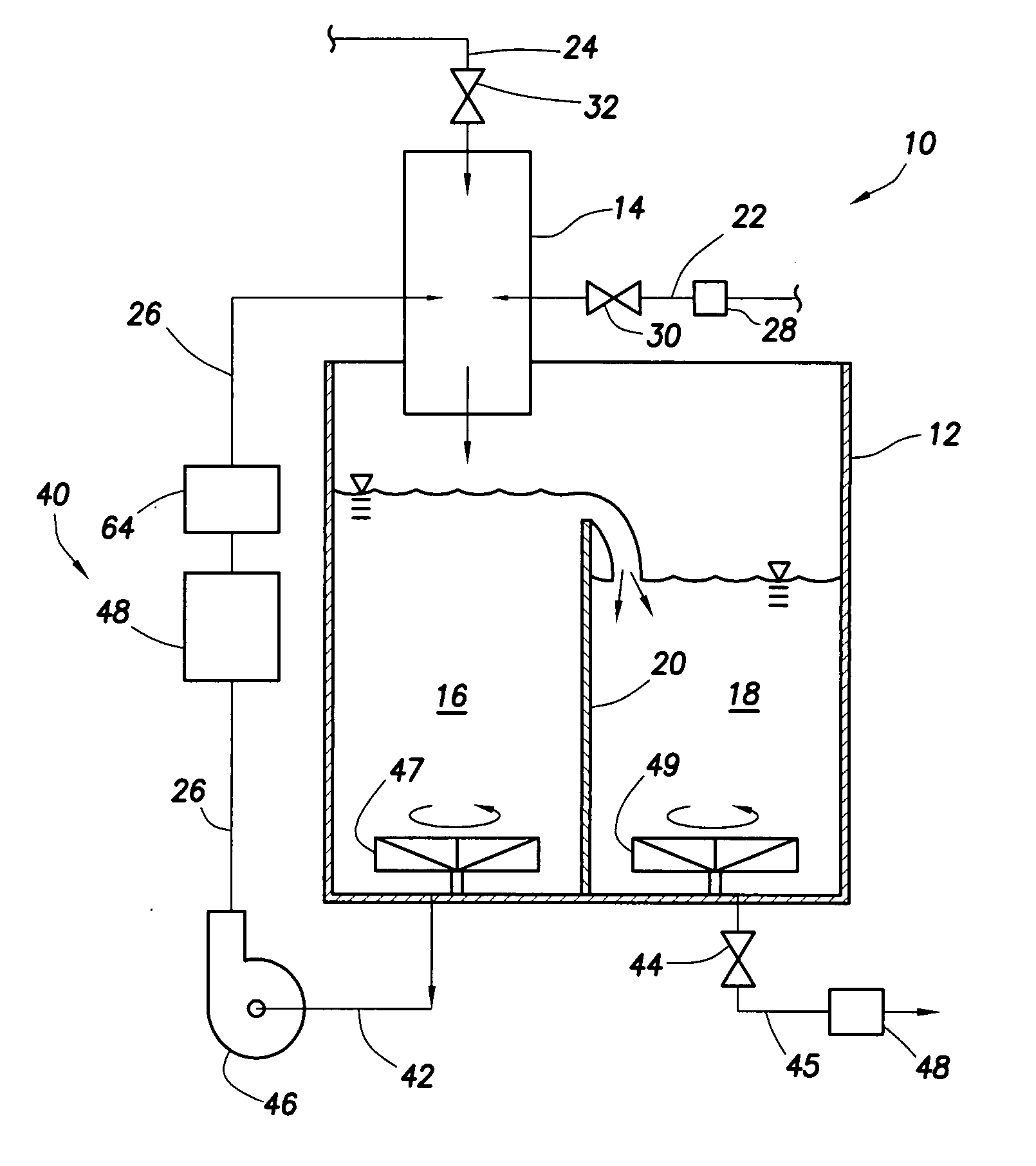
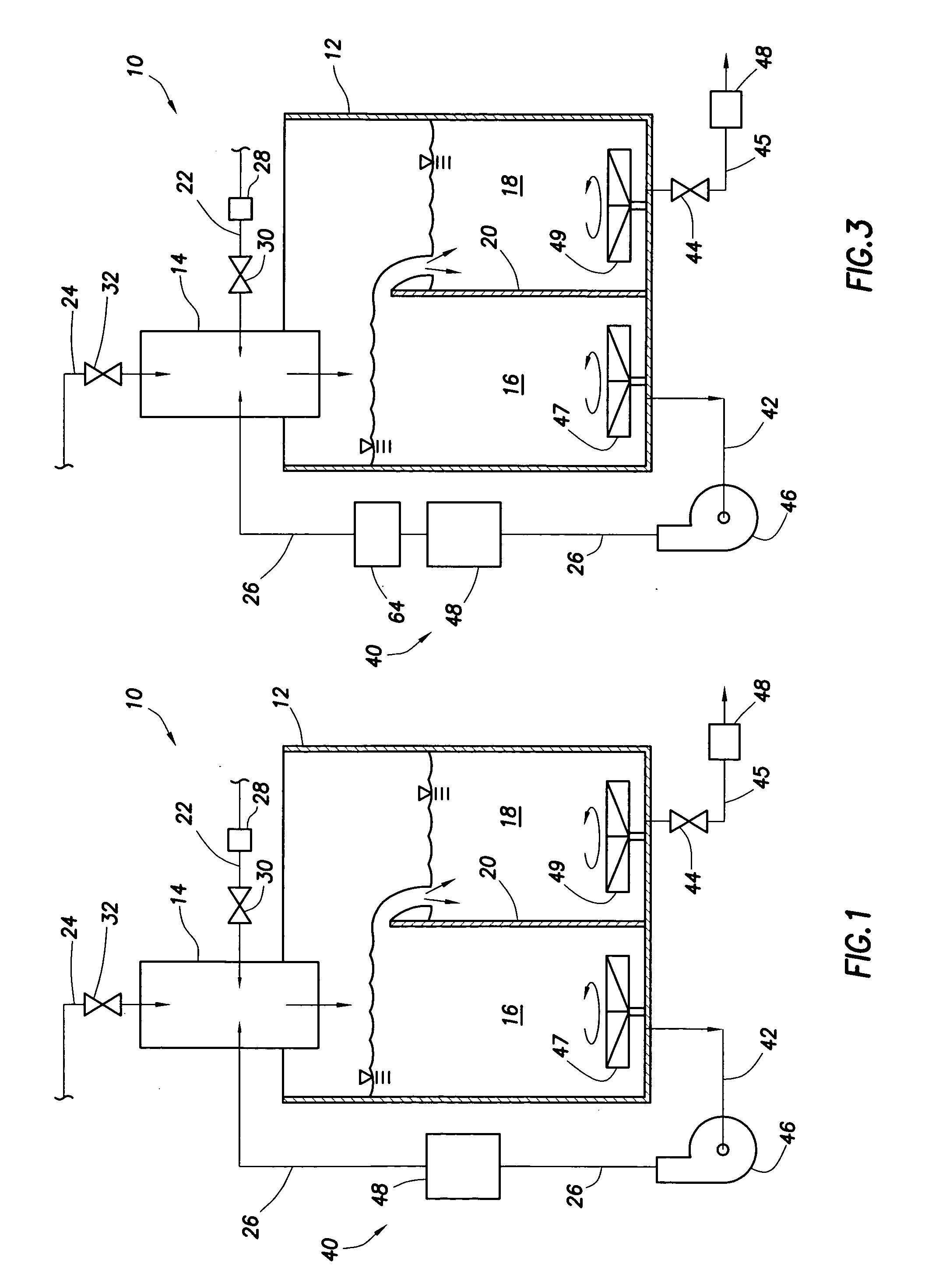
[0017] The details of the present invention will now be described with reference to the accompanying figure. Turning to FIG. 1, a system for mixing a fluid comprising water and at least one non-aqueous material is referred to generally by reference numeral 10. The system 10 comprises a mixing tub 12 and a mixing head 14. The mixing tub 12 has two compartments 16 and 18, which are separated by a weir 20. The mixing head 14 is placed over the first compartment 16, which is referred to as the pre-mix side. The fluid mixture, or slurry, is discharged from the second compartment 18, which is referred to as the down-hole side.

[0018] In one certain embodiment, the mixing head 14 is a Halliburton RCM II, RCM IIe, or RCM IIIr mixing head. As those of ordinary skill in the art will appreciate, however, other suitable mixing heads can be used. In its simplest embodiment, the mixing head 14 has three input ports for receiving inputs from flow lines 22, 24, and 26, respectively. However, as tho...


PUM

PropertyMeasurementUnit
densitiesaaaaaaaaaa
densityaaaaaaaaaa
densityaaaaaaaaaa

Abstract

The present invention is directed to a system and method for mixing a fluid comprising water and at least one non-aqueous material. The system comprises a mixing tub and mixing head adapted to inject the fluid into the mixing tub. It also includes a plurality of lines connected to the mixing head that supply the mixing head with water and the at least one non-aqueous material and a recirculation circuit that delivers the fluid from the mixing tub back to the mixing head. The system further includes a sensor connected to the recirculation circuit that measures the concentration of water in the fluid. An automatic controller uses the concentration measurement data to control the amount of each of the ingredients injected into the mixing tub.

Description

FIELD OF THE INVENTION [0001] The present invention relates generally to systems for preparing a mixture of a water and at least one non-aqueous material, and more particularly to a system and method for batch and continuous mixing of such materials using measured water concentration to control the addition of ingredients. BACKGROUND OF THE INVENTION [0002] In the drilling of oil and gas wells, it is often necessary to place cement or some other material around the outside of casing to protect the casing and prevent movement of formation fluids behind the casing. The cement is typically mixed in a mixer at the surface and pumped down hole and around the outside of the casing. The mixing is typically done by combining the cement ingredients, typically water, cement, and other non-aqueous materials until the proper density is obtained, and then continuing to mix as much material as needed at that density while pumping down hole in a continuous process. The process has been automated b...

Claims


Application Information

Patent Timeline
Patent Type & Authority Applications(United States)
IPC IPC(8): B01F3/12B01F5/00B01F5/10B01F15/00B01F15/02B28C7/02G01N27/04G01N33/38G05D11/13
CPCB01F3/1221B01F5/106B01F7/167B01F15/0408B01F15/0022B01F15/00344B01F7/18B01F23/53B01F25/53B01F27/851B01F27/90B01F35/2132B01F35/2211B01F35/82
Inventor DUELL, ALAN B.BLASCHKE, KEITH E.
Owner HALLIBURTON ENERGY SERVICES INC
Why Eureka
Try Eureka