
Postoperative fluid monitoring and alert system

a technology of alert system and fluid monitoring, applied in the direction of suction device, suction drainage container, other medical devices, etc., can solve the problems of lack of automated control, simple structure, endanger patient's life,

Inactive Publication Date: 2005-09-15
HAEMONETICS
View PDF13 Cites 62 Cited by
  • Summary
  • Abstract
  • Description
  • Claims
  • Application Information

AI Technical Summary

Benefits of technology

The present invention provides a system for monitoring and analyzing the performance of a surgical wound drainage procedure. The system includes a fluid collection device with a vacuum reservoir and a suction pathway for collecting fluid from the surgical site. The collected fluid is then returned to the patient for disposal or further processing. The system also includes sensors and a controller to monitor and analyze the fluid collection process. The controller can identify potential problems with the procedure and activate an alarm to alert caregivers. The system can be used in both peri-operative and intra-operative modes and can be connected to a vacuum pump to replenish the suction pathway. The system provides valuable information for caregivers to assess the progress of patient recovery and surgical wound healing.

Problems solved by technology

Without proper drainage, the pooling of blood and fluid in the chest cavity can prevent the lungs from fully expanding to allow normal breathing, which could endanger a patient's life.
Commonly used devices for managing the collection of blood and fluid from a surgical site in a postoperative environment are disposable, relatively simple and lack automated controls.
Continuing high amounts of fluid collection or a sudden increase in fluid collection after a period of reduced amounts of collected fluid may indicate bleeding at the surgical site that requires attention of the care provider.
Because the known manual collection devices mentioned above lack automated controls, the progress of fluid collection must be monitored actively by the care provider.
Such labor-intensive monitoring is wasteful of the care provider's time and endangers the patient because problems that arise between observation visits will not be noticed until the next regularly scheduled status check is made by the care provider.

Method used


Image

  • Postoperative fluid monitoring and alert system
  • Postoperative fluid monitoring and alert system
  • Postoperative fluid monitoring and alert system

Examples


Embodiment Construction

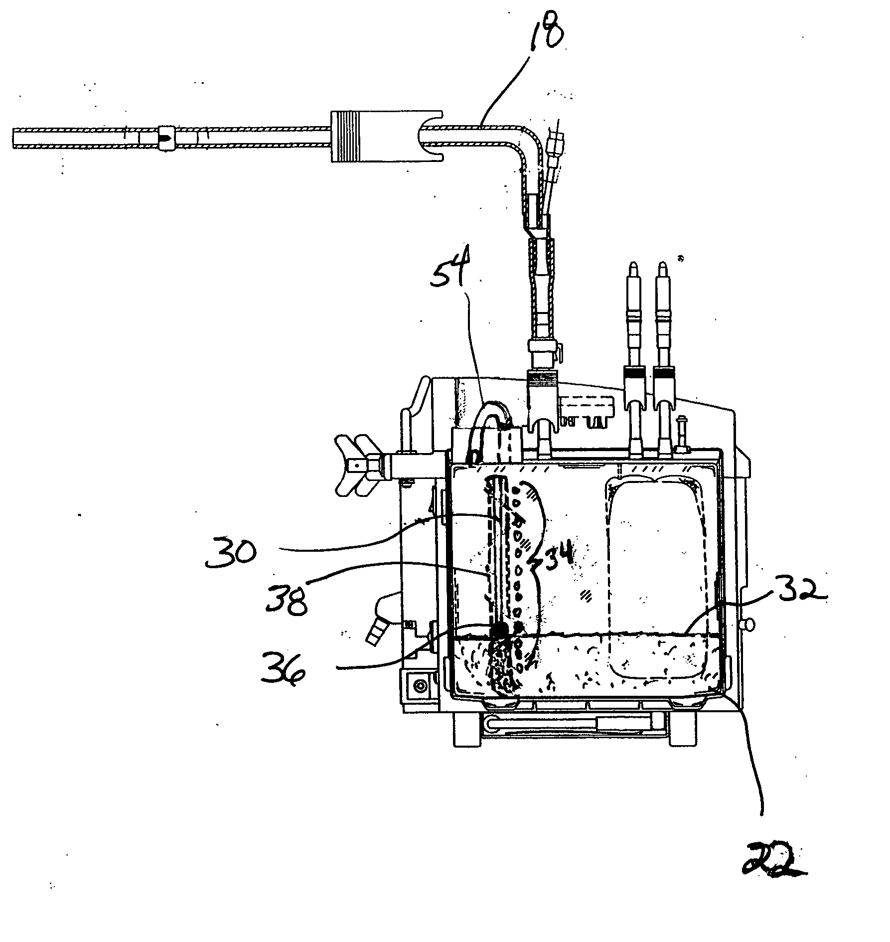
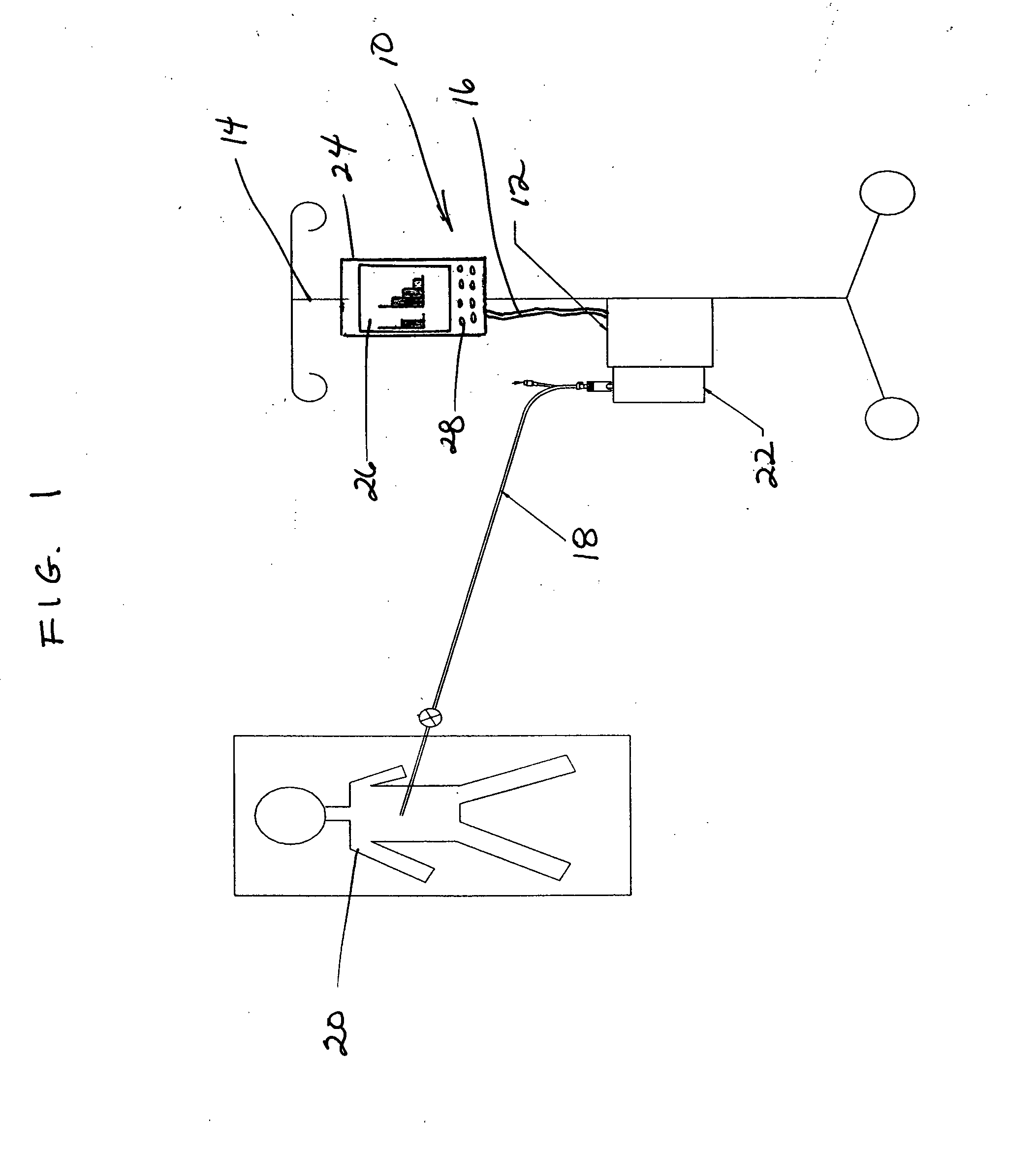
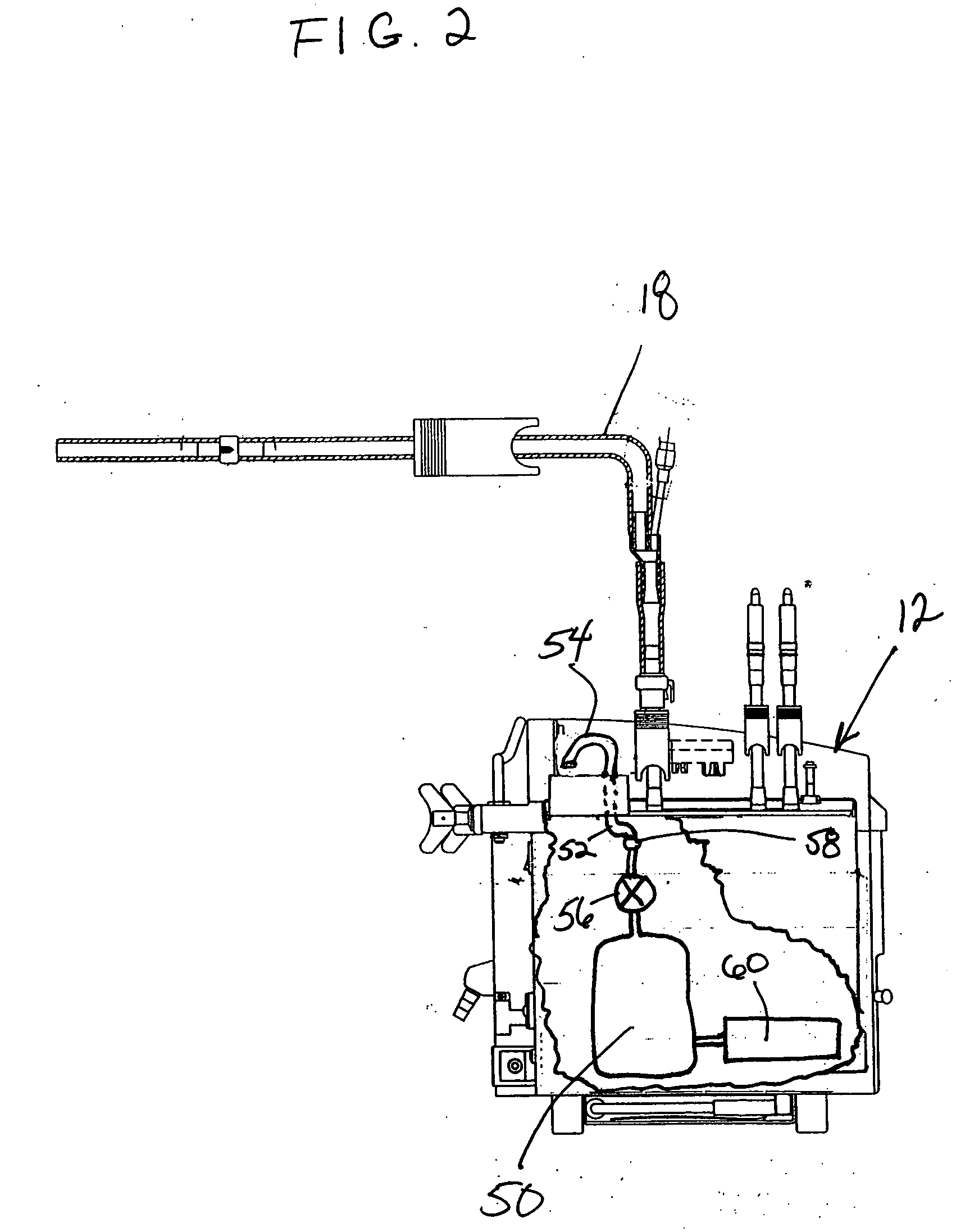
[0031]FIG. 1 shows a diagrammatical illustration of a postoperative fluid monitoring and alert system 10 in combination with a fluid collection device 12. The monitoring and alert system 10 may be mounted together with the collection device 12, such as on an I.V. pole 14, and connected together by a communication conduit 16 such as wiring. The fluid collection device 12 is joined to a surgical wound drain tube 18 that leads to a drain catheter (not shown) positioned internally at the surgical site of a patient.

[0032] During a surgical drainage procedure, suction is applied to a fluid collection vessel 22 of the fluid collection device 12 and to drain tube 18 to aspirate blood and other fluids through the drain catheter placed at the surgical site. Interior passages of the drain catheter, drain tube, collection vessel and collection device define a suction pathway through which fluid can be aspirated from the surgical site. Fluids collected at postoperative surgical site include liq...


PUM


Abstract

Continuous performance monitoring and an automated alert system are provided for a postoperative fluid drainage procedure. The system uses an automated controller in communication with at least one sensor that monitors the amount of liquid collected during the procedure. The controller compares current collection data with historical collection data to identify trends that can be indicative of problems in the patient's recovery or in system drainage. Upon identifying such trends, the controller automatically provides an alarm to alert the care provider so that the system can be checked and remedial action taken.

Description

FIELD OF THE INVENTION [0001] This invention pertains to devices and methods for postoperative collection of blood and other fluids from a surgical site. In particular, the invention relates to a system for monitoring such procedures and providing means for alerting a care provider of changes in drainage status. BACKGROUND OF THE INVENTION [0002] Postoperative drainage of blood and other fluids that tend to collect at a surgical site is necessary to promote proper healing and prevent harm to surrounding tissues and organs. Drainage at the surgical site is particularly important in procedures carried out in the chest cavity, such as cardiac or spine procedures. Without proper drainage, the pooling of blood and fluid in the chest cavity can prevent the lungs from fully expanding to allow normal breathing, which could endanger a patient's life. [0003] Commonly used devices for managing the collection of blood and fluid from a surgical site in a postoperative environment are disposable,...

Claims


Application Information

Patent Timeline
Patent Type & Authority Applications(United States)
IPC IPC(8): A61M1/00
CPCA61M1/0003A61M1/0023A61M2205/3389A61M2205/3331A61M2205/3379A61M1/0049A61M1/78A61M1/73A61M1/66A61M1/982A61M1/777
Inventor BOBROFF, ALECMARTIN, CLIFFORD ROSSDOLLIVER, PHILLIP B.
Owner HAEMONETICS
Learn More