Method and system for providing interactive testing of integrated circuits

a technology of integrated circuits and interactive testing, applied in the field of testing integrated circuits, can solve the problems of large, insufficient and ineffective diagnostic pattern sets, complex semiconductor process intensification, and new types of defects introduced by the time, and the fault simulators are typically imper

Inactive Publication Date: 2005-09-15
IBM CORP
View PDF9 Cites 7 Cited by
  • Summary
  • Abstract
  • Description
  • Claims
  • Application Information

AI Technical Summary

Benefits of technology

[0007] One aspect of the invention is a method for testing an integrated circuit. The method includes receiving a first failing region. The first failing region corresponds to one or more circuits on the integrated circuit. A set of adaptive algorithmic test patterns is generated for the one or more circuits in response to the first failing region and to a logic model of the integrated circuit. Expected results for the test patterns are determined by simulation or from actual “good” devices. The method also includes applying the test patterns to the first failing region on the integrated circuit resulting in actual results for the test patterns. The expected results are compared to the actual results. Mismatches between the expected results and the actual results are transmitted to a fault simulator. A second failing region is received from the fault simulator, where the second failing region was created in response to the mismatches and the logic model. The second failing region corresponds to a subset of the one or more circuits on the integrated circuit.
[0008] Another aspect of the invention is a computer program product for testing an integrated circuit. The computer program product includes a storage medium readable by a processing circuit and storing instructions for execution by the processing circuit for performing a method that includes receiving a first failing region. The first failing region corresponds to one or more circuits on the integrated circuit. A set of algorithmic test patterns for the one or more circuits is generated in response to the first failing region and to a logic model of the integrated circuit. The method determines expected results for the test patterns. The test patterns are applied to the first failing region on the integrated circuit resulting in actual results for the test patterns. The expected results are compared to the actual results. Mismatches between the expected results and the actual results are transmitted to a fault simulator. A second failing region is received from the fault simulator, where the second failing region was created in response to the mismatches and the logic model. The second failing region corresponds to a subset of the one or more circuits on the integrated circuit.
[0009] A further aspect of the invention is a system for testing an integrated circuit. The system includes a programmable pattern generator. The system also includes a bootstrapping module that is in communication with the integrated circuit. A test controller is in communication with the programmable pattern generator, the bootstrapping module, the integrated circuit, and a fault simulator. The fault simulator includes a logic model of the integrated circuit. The test controller includes instructions to execute a method that includes receiving a first failing region. The first failing region corresponds to one or more circuits on the integrated circuit. A set of algorithmic test patterns is generated by the programmable pattern generator for the one or more circuits in response to the first failing region and to the logic model. The expected results for the test patterns are determined and captured by the bootstrapping module. The test patterns are applied to the first failing region on the integrated circuit resulting in actual results for the test patterns. The bootstrapping module captures the actual expected results and the expected results which are compared to the actual failing results. Mismatches between the expected results and the actual results are transmitted to the fault simulator. A second failing region is received from the fault simulator, where the second failing region was created in response to the mismatches and the logic model. The second failing region corresponds to a subset of the one or more circuits on the integrated circuit. The process can be iterative in nature.

Problems solved by technology

A problem often encountered in testing, and the subsequent diagnosis, of very large-scale integration (VLSI) devices is the availability of effective test patterns for a broad range of modeled and un-modeled faults.
The rapid integration growth of VLSI devices, associated high circuit performance, and complex semiconductor processes has intensified old and introduced new types of defects.
This defect diversity and subtlety, accompanied by limited fault models, usually results in large, insufficient and ineffective diagnostic pattern sets.
The results determined by the fault simulators are typically imperfect, in that they contain several (in many cases dozens) diagnostic calls that may need to be investigated in order to pinpoint the cause(s) of the failure.

Method used


Image

  • Method and system for providing interactive testing of integrated circuits
  • Method and system for providing interactive testing of integrated circuits
  • Method and system for providing interactive testing of integrated circuits

Examples


Embodiment Construction

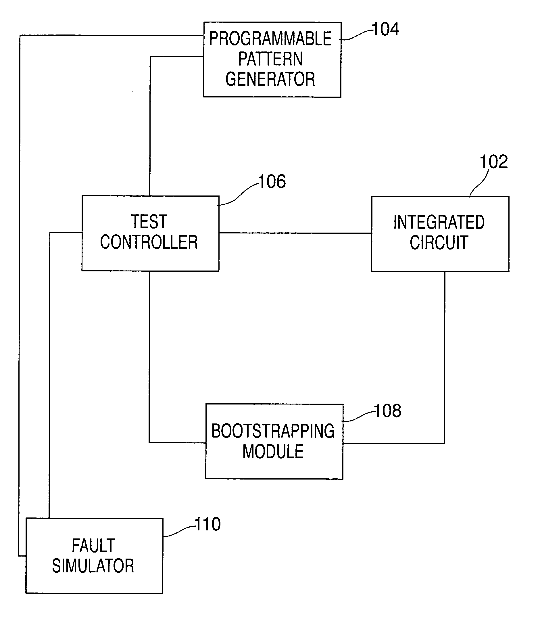
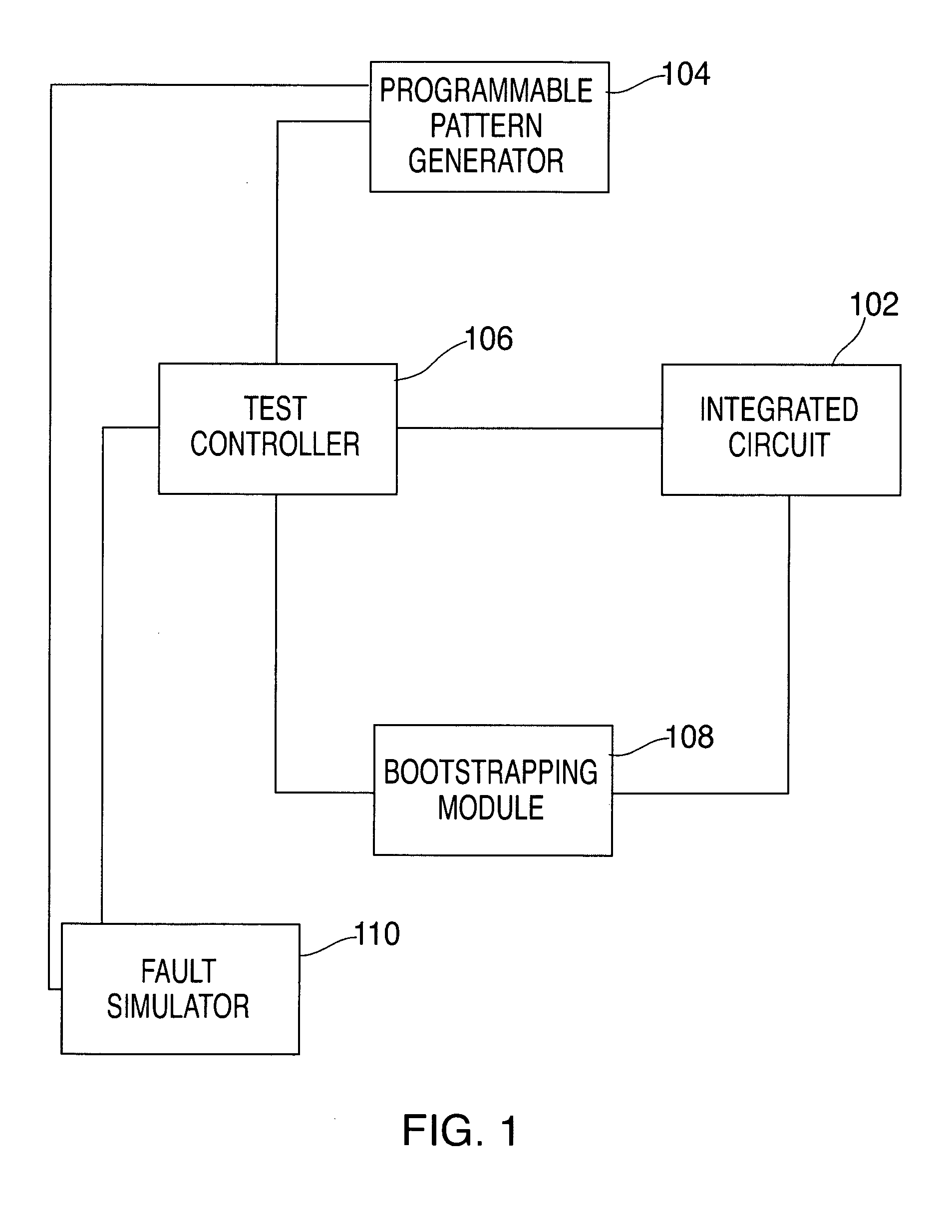
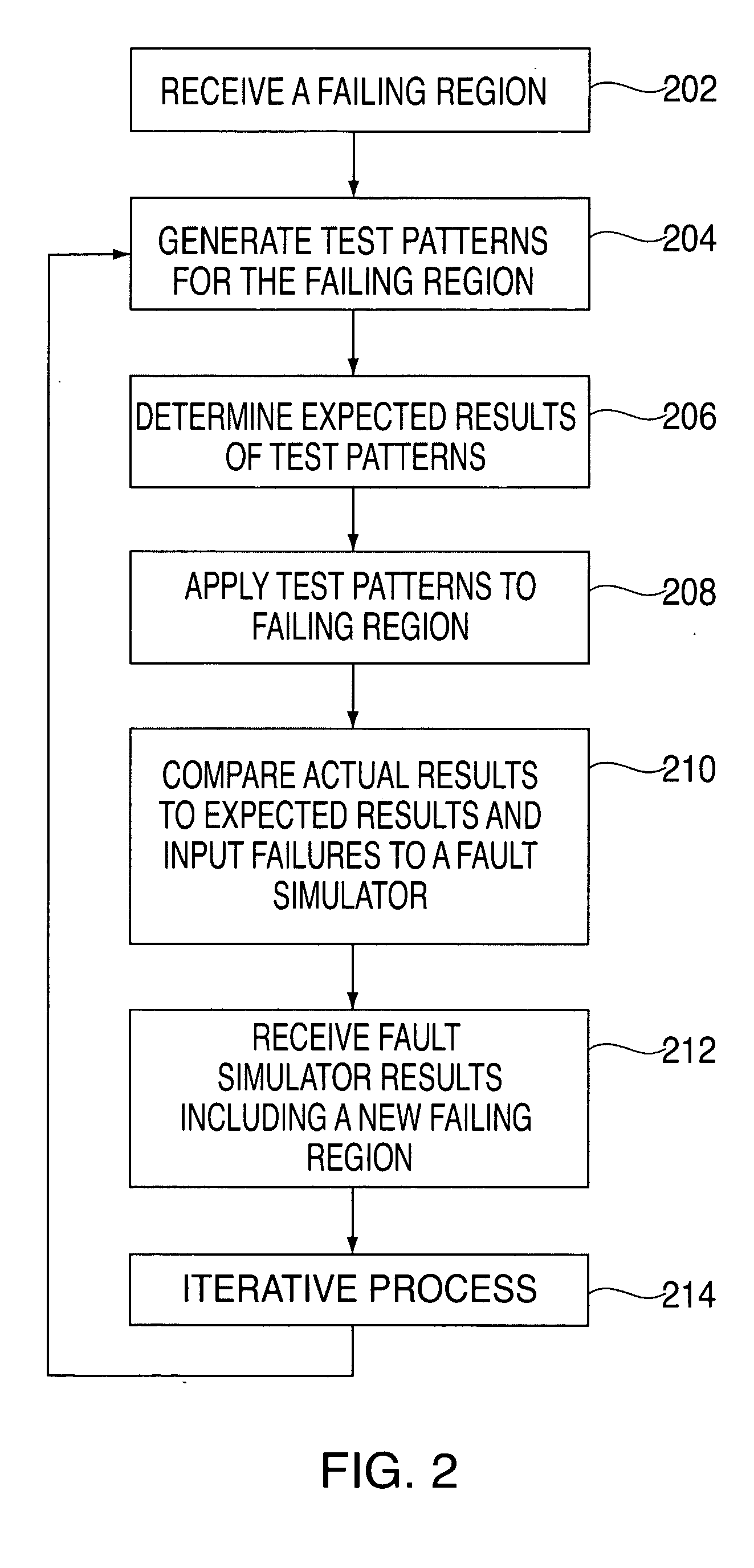
[0015] An exemplary embodiment of the present invention includes a novel test, characterization and diagnostic method applicable to logic designs. It addresses the problems of fault isolation and diagnostic resolution by providing an adaptive test algorithm and a tester interactive pattern generator method in conjunction with on-the-fly bootstrapping techniques. The test and diagnostic method is used to identify defects and pattern sensitivities within a specific logic partition. This is accomplished by applying a pre-determined set of patterns to the logic in both an operating region and a failing region. The bootstrapped results from the operating region are compared to the results in the failing region to determine if the pattern passes or fails. In alternate exemplary embodiments, the basic concept is further extended to encompass interactively simulated patterns to optimize the diagnostic convergence process. Also, in situations where a “passing” operation region is not readily...


PUM


Abstract

A method for providing interactive and iterative testing of integrated circuits including the receiving of a first failing region. The first failing region corresponds to one or more circuits on the integrated circuit. The method generates a set of adaptive algorithmic test patterns for the one or more circuits in response to the first failing region and to a logic model of the integrated circuit. Expected results for the test patterns are determined. The method includes applying the test patterns to the first failing region on the integrated circuit resulting in actual results for the test patterns. The expected results to the actual results are compared. The method also transmits mismatches between the expected results and the actual results to a fault simulator. The method includes receiving a second failing region from the fault simulator, the second failing region created in response to the mismatches and the logic model, and the second failing region corresponding to a subset of the one or more circuits on the integrated circuit.

Description

BACKGROUND OF THE INVENTION [0001] The invention relates to testing integrated circuits and in particular to a diagnostic utility for identifying defects and test pattern sensitivities in semiconductor logic. [0002] Several design, test and diagnostic methodologies have evolved over the years in support of structural and functional test methods. Some of the integrated circuit designs integrate this support onto the device itself. These built-in self-test (BIST) and diagnostic functions are based on several design for test (DFT) techniques such as scan design (e.g., level sensitive scan design (LSSD) and general scan design (GSD)), logic and array built-in-self-test (LBIST and ABIST), on-product clock generation (OPCG), and others. [0003] The LSSD test and diagnostic methodology has been widely used for many years. It is based on the concept of “divide-and-conquer” whereby large sequential logic structures are divided into smaller combinatorial partitions. The LSSD methodology is a s...

Claims


Application Information

Patent Timeline
Patent Type & Authority Applications(United States)
IPC IPC(8): G01R31/28G06F11/00
CPCG01R31/31703G06F11/263G06F11/261G01R31/318371
Inventor BURDINE, TODD M.MOTIKA, FRANCOSONG, PEILIN
Owner IBM CORP
Why Eureka
Try Eureka