Method for diagnosing failures using invariant analysis

a failure and invariant analysis technology, applied in error detection/correction, program control, instruments, etc., can solve the problems of measurable states, inability to observe errors, and inability to achieve measurable states, so as to reduce the time required

Inactive Publication Date: 2002-08-29
CADENCE DESIGN SYST INC
View PDF0 Cites 7 Cited by
  • Summary
  • Abstract
  • Description
  • Claims
  • Application Information

AI Technical Summary

Benefits of technology

[0013] It is yet another object to quickly identify a small set of stuck fault failure candidates in order to improve the performance of traditional stuck fault diagnostics.

Problems solved by technology

However, after the pulse, the effects of the error are not as observable.
Therefore, the scores calculated by invariant analysis are not representative of what is truly occuring in the circuit.
In general, the introduction of memory elements introduces many measurable states, and can be much more complicated.
However, for cases where the dominant net is at the same value as the dominated net, a stuck fault on the dominated net will predict a failure which is not measured.
Traditional diagnostics depends on simulating many candidate faults for many patterns, which is very expensive.

Method used


Image

  • Method for diagnosing failures using invariant analysis
  • Method for diagnosing failures using invariant analysis
  • Method for diagnosing failures using invariant analysis

Examples


Embodiment Construction

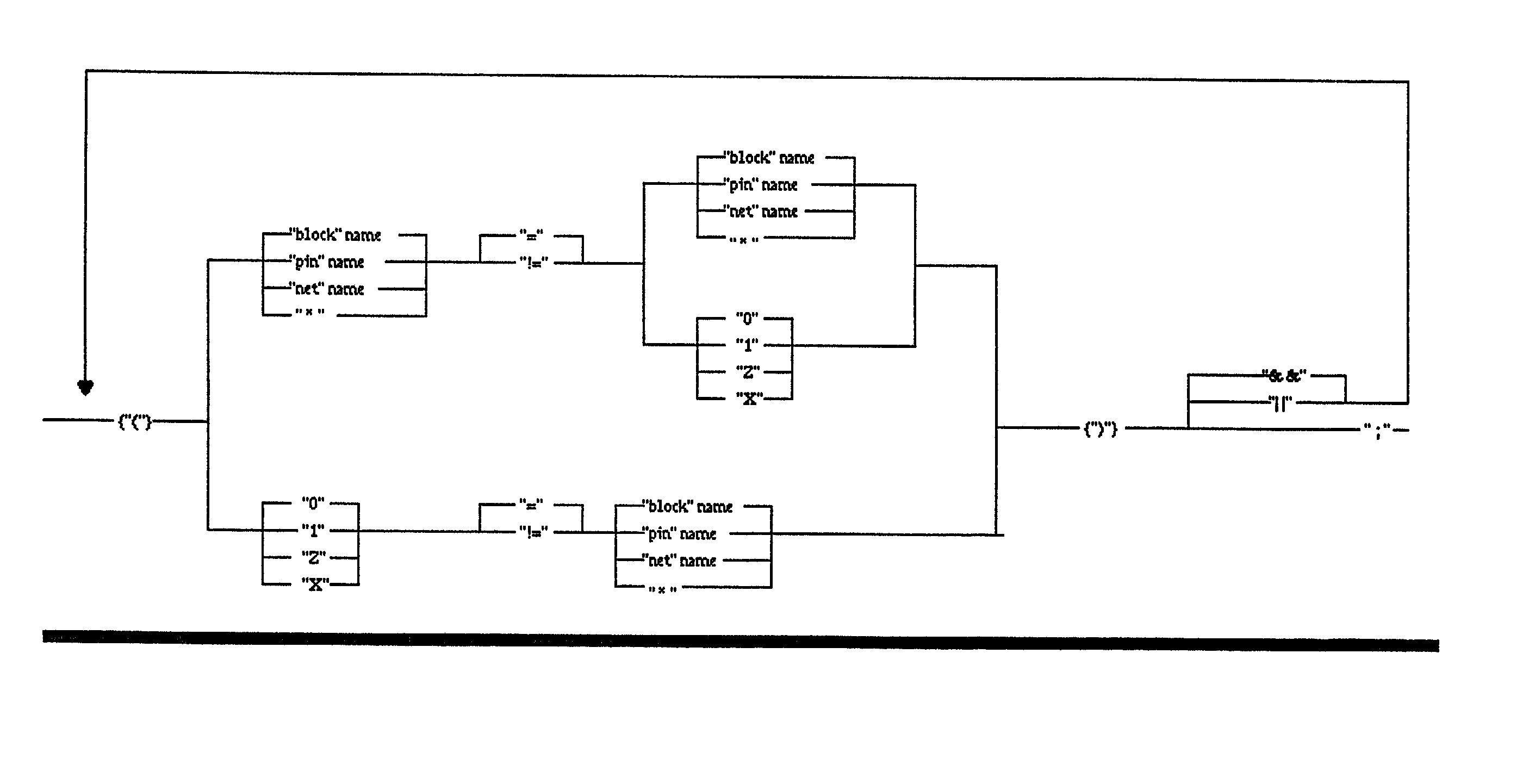
[0024] The inventive method describes an IC represented by a set of pins and nets. The software has access to a schematic model of the integrated circuit, the test patterns used to test the circuit, and information about which test patterns failed at the tester when the integrated circuit was tested. The user of the software provides queries about the failing circuit in the form of boolean equations that describe specific conditions in the circuit. The software simulates the test patterns using the schematic model of the circuit to produce expected results as the outputs of the circuit, as well as information concerning the internal circuit states of the schematic model. Thie simulation is compared with the boolean equations to determine the "truth value" of the equations. The equations are true or false in a specific circuit state. Since the information about which test patterns fail s is also available to the software, it can evaluate for each circuit state of interest whether an ...


PUM


Abstract

A method for diagnosing failures within an integrated circuit where known diagnostic fault simulators are unable to detect failure mechanisms which do not conform to known failure models. Basic boolean equations are used to describe the internal nodes forming the logic. These equations are then evaluated by way of a good machine simulation to determine which of the equations are (most) true for failing test patterns and (most) false for passing patterns. At the end of the good machine simulation a score is calculated to determine the number of times (or percentage) for which the equation is true for failing patterns and false for passing patterns. The method is particularly effective for finding shorted nets pairs in which the failure mechanism does not fall within known models. The method described is instrumental in greatly reducing the time required for manual analysis of failure mechanisms not conforming to known models.

Description

FIELD OF THE INVENTION[0001] The invention relates generally to electronic design automation, and more particularly to testing and diagnosing failures within an integrated circuit (IC) to determine the cause of the IC failing to perform as expectedBACKGROUND AND PRIOR ART[0002] The process of determining the root cause of a failing integrated circuit has been vital to the timely and cost effective production of integrated circuits for many years. If the cause of a failure can be determined, the error which causes the failure can often be corrected or prevented from reoccurring. Information about the root cause of the problem can lead to improvements in the design process, the design itself, the manufacturing process, and the test process. It has long been recognized that the capability to determine the root cause of a failure is vital to achieve and maintain high yields in manufacturing, and the manufacturing yields directly affect the cost of manufacturing integrated circuits. The ...

Claims


Application Information

Patent Timeline
Patent Type & Authority Applications(United States)
IPC IPC(8): G01R31/3183
CPCG01R31/318342
Inventor BARTENSTEIN, THOMAS W.SWENTON, JOSEPH M.
Owner CADENCE DESIGN SYST INC
Why Eureka
Try Eureka