Generic design approach for multi-layer architecture

Inactive Publication Date: 2005-09-15
RAMCO SYSTEMS
View PDF5 Cites 35 Cited by
  • Summary
  • Abstract
  • Description
  • Claims
  • Application Information

AI Technical Summary

Problems solved by technology

While software applications in a computer information system are normally broken into subsystems or components for modularity and ease of development, the resulting system is ironically complex because the multiple components, multiple layers, and multiple systems and sub-systems that are deployed across multiple machines or nodes, all may require either direct or indirect access to each other.
However, in multi-component architectures it becomes difficult to handle such hard-coded location and routing requirements.
Again, because this distribution might cross machine, node, and system boundaries, it will in all likelihood introduce further routing complications which are very difficult to keep track of if hard-coding is used.
However, one of the very reasons for instrumenting information systems, i.e. the need to determine how the system operates over its many components, layers, systems and subsystems, and machines and nodes, itself causes difficulties in the actual instrumenting of the information system.
This presents a Catch-22 to a system opera

Method used


Image

  • Generic design approach for multi-layer architecture
  • Generic design approach for multi-layer architecture
  • Generic design approach for multi-layer architecture

Examples


Embodiment Construction

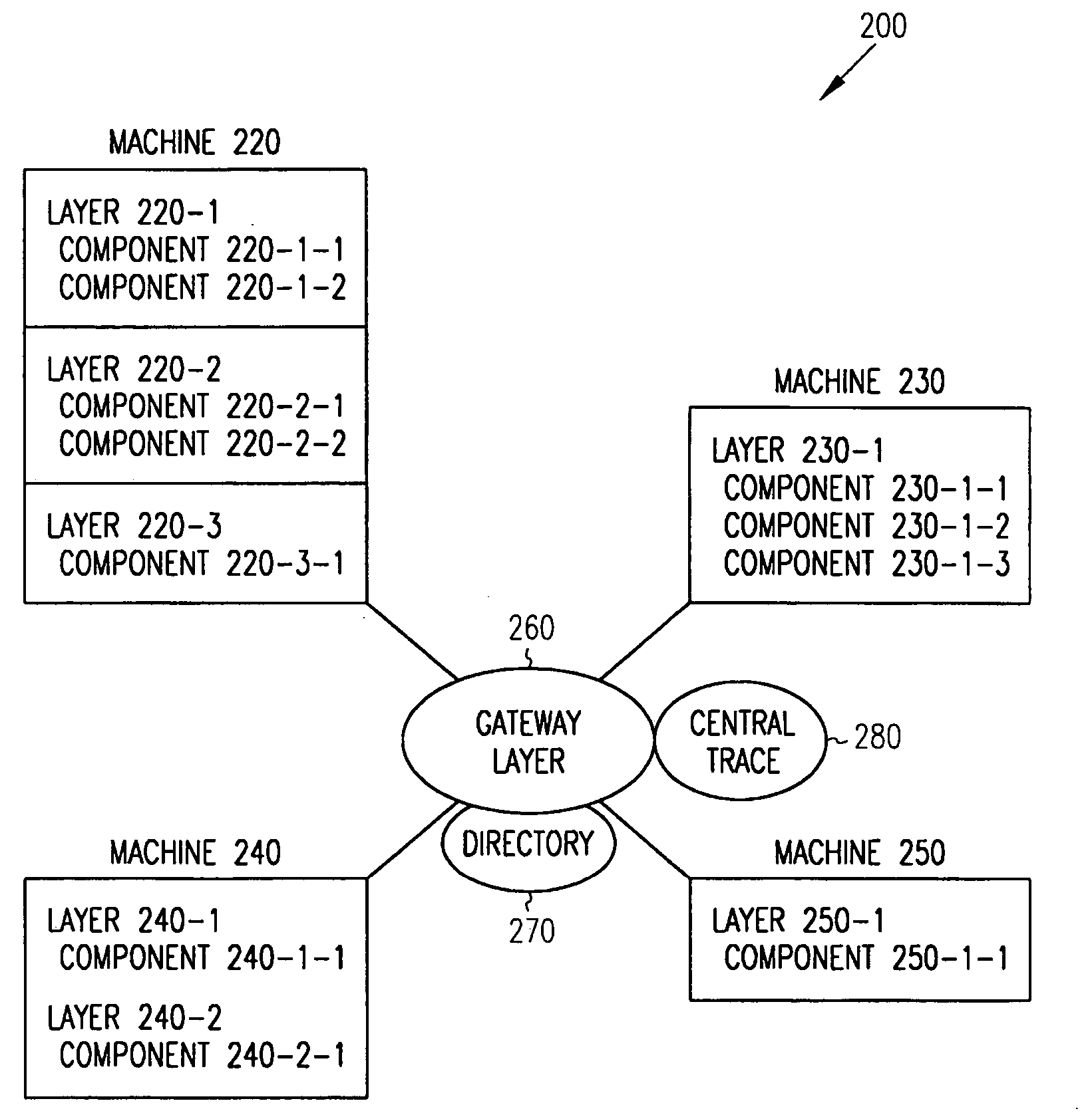
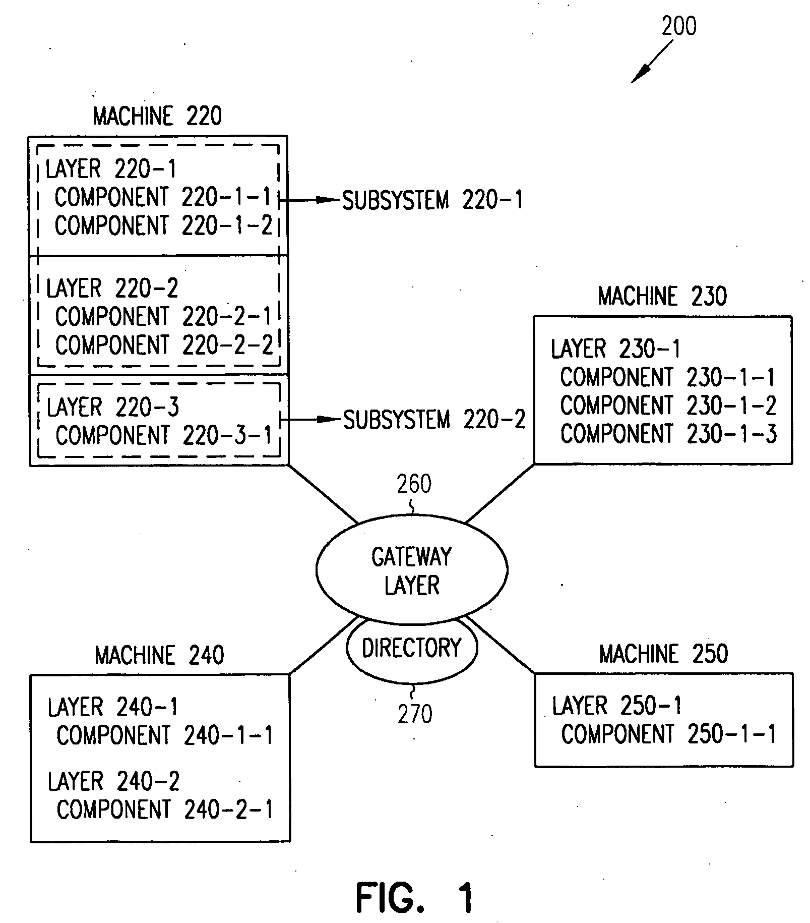
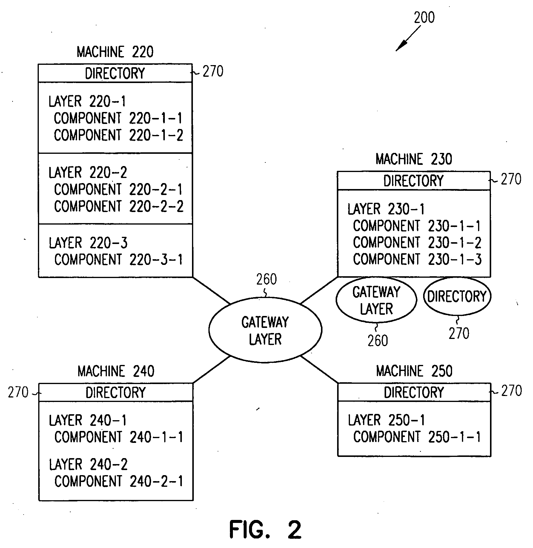
[0018] In one embodiment of the present invention, a gateway layer is introduced into an information system to implement a platform independent routing architecture for systems with multiple components, layers, systems / subsystems, and machines / nodes. The gateway layer provides the necessary interfaces for locating and routing the service requests from and to each and every component in the system, and it serves as a common entry point to both internal service requests (i.e. within a layer or subsystem) and external service requests (i.e. from other systems or machines).

[0019] The gateway layer uses a software model driven approach to derive the location information of each component and the same is populated into a directory. In this instance, a software model driven approach refers to modeling every significant part of the system as data and using that data in the gateway layer. Because a software model-driven approach for development and deployment is used, the details about all ...


PUM


Abstract

A method affords the design of a generic structure for a deployment topology and deployable artifact (executable code) packages. After completion of the design, the artifact packages are mapped over the generic topology structure, component information is uploaded into a directory, and the directory used to route service requests. In another embodiment, a method affords the design of a generic structure for system services and user interfaces. After the design, semantics are abstracted and used to data bind the system services and the user interfaces. In another embodiment, a computer information system is described having a gateway layer that permits platform independent deployment and ease of request routing.

Description

RELATED APPLICATIONS [0001] Benefit is claimed under 35 U.S.C. 119(e) to U.S. Provisional Application Ser. No. 60 / 553,639, filed Mar. 16, 2004, which is herein incorporated in its entirety by reference for all purposes. [0002] Benefit is claimed under 35 U.S.C. 119(e) to U.S. Provisional Application Ser. No. 60 / 553,086, filed Mar. 15, 2004, which is herein incorporated in its entirety by reference for all purposes. [0003] Benefit is claimed under 35 U.S.C. 119(e) to U.S. Provisional Application Ser. No. 60 / 553,682, filed Mar. 16, 2004, which is herein incorporated in its entirety by reference for all purposes. [0004] Benefit is claimed under 35 U.S.C. 119(e) to U.S. Provisional Application Ser. No. 60 / 553,632, filed Mar. 16, 2004, which is herein incorporated in its entirety by reference for all purposes.FIELD OF THE INVENTION [0005] The present invention relates to computer information systems, and in particular, a generic design approach for computer information systems that have ...

Claims


Application Information

Patent Timeline
IPC IPC(8): G06F9/44G06F9/445
CPCG06F8/61G06F2209/547G06F9/546
Inventor SUNDARARAJAN, PARTHASARATHYJAYARAMAN, SHYAMALASATHIAVAGEESWARAN, SURESHKRISHNAN, NATARAJANKRISHNAKISHORE, BHAVARAJU V.RAJA, PUSAPADI RAMASUBRAMANIA RAJA VENKETRAMA
Owner RAMCO SYSTEMS
Why Eureka
Try Eureka