Imaging tomography apparatus having an attached patient support with a movable backrest

Inactive Publication Date: 2005-09-22
SIEMENS AG
View PDF9 Cites 3 Cited by
  • Summary
  • Abstract
  • Description
  • Claims
  • Application Information

AI Technical Summary

Benefits of technology

[0006] An object of the invention to provide an imaging tomography apparatus that avoids the aforementioned disadvantages. In particular, such an imaging tomography apparatus should enable improved access t

Problems solved by technology

A problem thus sometimes occurs that the surgery region of the patient i

Method used


Image

  • Imaging tomography apparatus having an attached patient support with a movable backrest
  • Imaging tomography apparatus having an attached patient support with a movable backrest
  • Imaging tomography apparatus having an attached patient support with a movable backrest

Examples


Embodiment Construction

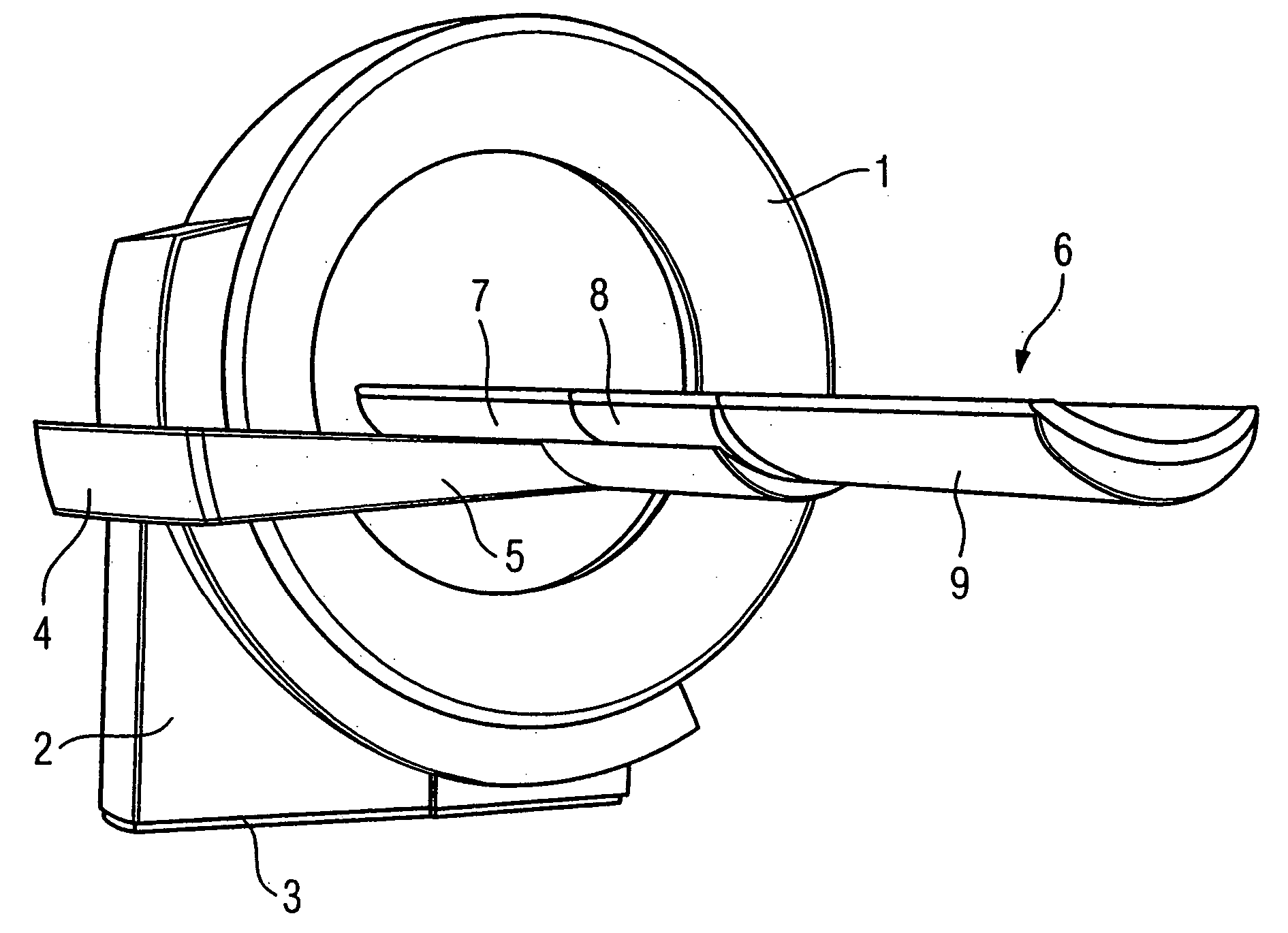
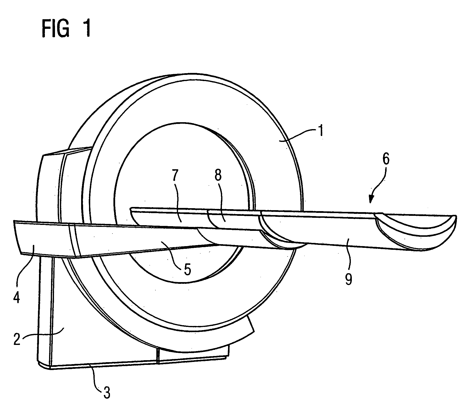
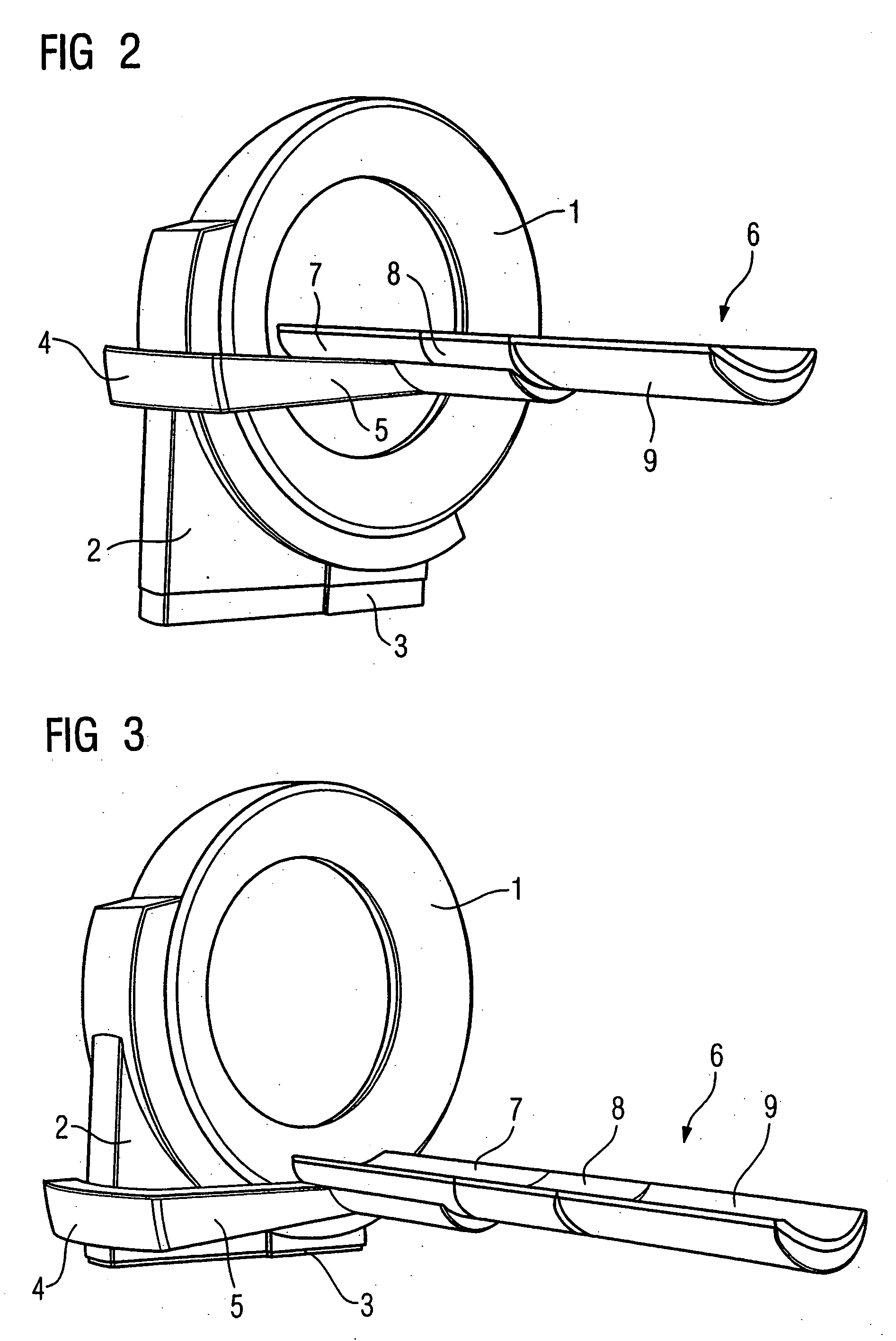
[0018] A tomography apparatus is shown in FIGS. 1 through 5 in the example of an x-ray computed tomography apparatus. An annularly fashioned data acquisition device or gantry 1 is accommodated on a carrier 2. The carrier 2 is supported on a base 3 such that the carrier 2 can be moved vertically. In addition, a hydraulically-operable or electrically-operable lifting device (not shown) is provided. A mounting device 4 that can be moved vertically is in turn attached to the carrier 2. A mounting arm 5 of the mounting device 4 accommodates a-patient bed 6 such that it can move horizontally. The patient bed 6 can move horizontally, in particular parallel to the axis of the data acquisition device 1. As is best seen from FIG. 4, the patient bed 6 is formed of a backrest 7, a seat 8 and a foot part 9. For vertical movement of the mounting device 5, a further hydraulically-operable or electrically-operable lifting device (not shown) is provided. A preferably electrically-operable horizontal...


PUM


Abstract

An imaging tomography apparatus, such as an x-ray computed tomography apparatus or a magnetic resonance tomography apparatus, has a patient bed that can be driven into a tunnel-shaped or annular data acquisition device. To increase comfort for the patient and accessibility by medical personnel, the patient bed has a pivotable backrest connected to a seat.

Description

BACKGROUND OF THE INVENTION [0001] 1. Field of the Invention [0002] The present invention concerns an imaging tomography apparatus, in particular an x-ray computed tomography apparatus or magnetic resonance tomography apparatus of the type having a patient bed that is driven into and out of a data acquisition device (scanner). [0003] 2. Description of the Prior Art [0004] X-ray computed tomography and magnetic resonance tomography systems are known as imaging tomography apparatuses or systems. A common feature of such tomography apparatuses is a tube-shaped or tunnel-shaped data acquisition device (scanner). For data acquisition, the patient is horizontally moved into the scanner on a patient bed mounted at the tomography apparatus. The patient bed also can be vertically movable. This makes it easer to place the patient on the patient bed or to disembark after the scan, in particular for injured or elderly patients. [0005] In practice, sometimes a procedure must be conducted on the ...

Claims


Application Information

Patent Timeline
IPC IPC(8): A61B5/055A61B6/00A61B6/03A61B6/04G01N23/00G21K1/12H05G1/60
CPCA61B6/04
Inventor MAIER, SEBASTIANTHORMANN, KLAUS
Owner SIEMENS AG
Why Eureka
Try Eureka